A river channel dredging equipment with a silt water removal mechanism

A sludge and river channel technology, applied in the field of river channel dredging equipment, can solve the problems of increased mud volume, increased cost of transporting sludge, high moisture content of sludge, etc., and achieve the effect of improving the service life

Active Publication Date: 2022-04-29
绍兴柏莉建设有限公司
View PDF0 Cites 0 Cited by
  • Summary
  • Abstract
  • Description
  • Claims
  • Application Information

AI Technical Summary

Problems solved by technology

In addition, the low concentration of the blown mud slurry will lead to an increase in the volume of the mud, which will increase the area occupied by the sludge storage yard
[0007] The advantage of these dredging methods is that they can be carried out without draining the river, but they all have the problem of high water content in the sludge, which leads to a significant increase in the cost of transporting the sludge
[0008] For pump-type dredging equipment, in order to reduce the cost of transporting sludge, it is an ideal choice to filter the water in the sludge and then transport the sludge. However, ordinary filter equipment generally filters through filter cloth. During the process, the surface of the filter cloth will seep into the solid particles in the sludge. Long-term use will reduce the circulation efficiency of the filter cloth, making it impossible to quickly filter out the water in the sludge, which will affect the water filtration effect.

Method used


Image

  • A river channel dredging equipment with a silt water removal mechanism
  • A river channel dredging equipment with a silt water removal mechanism
  • A river channel dredging equipment with a silt water removal mechanism

Examples


Embodiment Construction

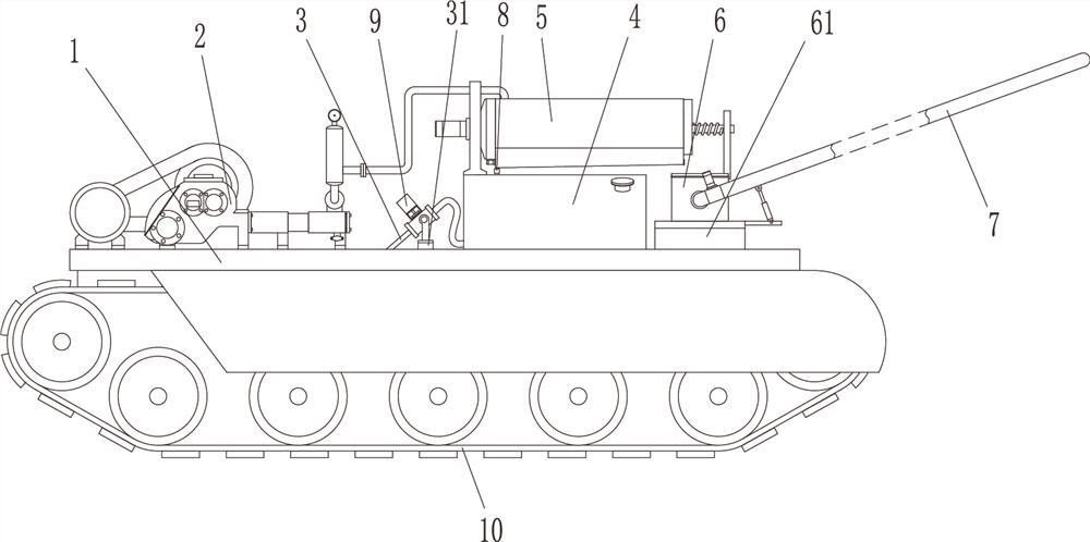
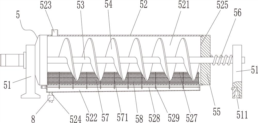
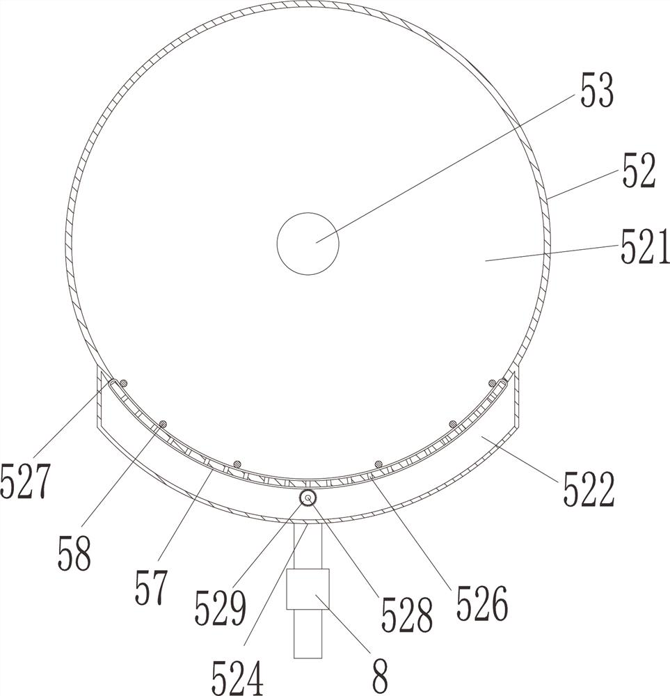
[0025] The present invention will be described in further detail below in conjunction with accompanying drawing and specific embodiment: see Figure 1 to Figure 4 , a river channel dredging equipment with a silt dewatering mechanism, comprising a frame 1, a mud pump 2 is arranged on the frame 1, a water gun 3, a water tank 4, and a silt dewatering device capable of continuous dewatering are arranged on the frame 1 Mechanism 5, dry silt tank 6 and dry silt conveying mechanism 7, a water pump (not shown in the figure) connected to the water gun 3 is arranged in the water tank 4, and the silt water removal mechanism 5 is provided with a silt inlet 523, a drain 524 and a silt discharge Port 525, the mud outlet of mud pump 2 is connected to mud inlet port 523, the drain port 524 is connected to water tank 4 through flow detection device 8, and the mud discharged from mud discharge port 525 falls into dry mud tank 6, and dry mud conveying mechanism 7 is connected to dry mud tank 6. ...


PUM


Abstract

The invention discloses a river channel dredging equipment with a silt water removal mechanism, which comprises a frame, a mud pump is arranged on the frame, a water gun, a water tank, a silt water removal mechanism capable of continuous water removal, a dry The sludge tank and the dry sludge conveying mechanism, the sludge dewatering mechanism includes a support frame, a shell, and an extruding spiral plate. Both ends of the extrusion chamber are provided with a sludge inlet and a sludge discharge port, and an extrusion plate is provided on the side of the sludge discharge port. There are several water outlet holes at the bottom of the pressure chamber, and two filter cloth passages are axially arranged on both sides of the extrusion chamber, and the filter cloth passes through the two filter cloth passages to connect end to end, and the bottom of the extrusion chamber is axially pierced There is a mechanism to drive the filter cloth to rotate, the sludge outlet of the mud pump is connected to the sludge inlet, the sludge discharged from the sludge discharge outlet falls into the dry sludge tank, and the dry sludge conveying mechanism is connected to the dry sludge tank. This kind of river channel dredging equipment can dewater the silt and then transport it to the carrier on the bank, and can use the filter cloth for a longer period of time without affecting its circulation efficiency.

Description

technical field [0001] The invention belongs to the technical field of river channel dredging equipment with a silt water removal mechanism, in particular to a river channel dredging device with a silt water removal mechanism, which is used for clearing silt in a river channel. Background technique [0002] During the construction of water conservancy projects, it is often necessary to excavate rivers, etc., and the treatment of silt in the river is one of the most important tasks. Effective treatment of these silts can better ensure water quality, and can also better reduce substances that pollute the environment, thus providing us with more For a good living environment, most of the harmful substances after water pollution are in the silt, so it is necessary to clean up the silt in the river regularly. [0003] The dredging equipment in the prior art generally includes grab bucket dredging, pump suction dredging and cutter suction dredging. [0004] Grab dredging is suita...

Claims


Application Information

Patent Timeline
Patent Type & Authority Patents(China)
IPC IPC(8): E02F3/88E02F3/90E02F3/92
CPCE02F3/8816E02F3/9262E02F3/907E02F3/902E02F3/9293
Inventor 丁柏根
Owner 绍兴柏莉建设有限公司
Why Eureka
Try Eureka