
Prefabricated bay window and connecting method

A bay window and prefabricated panel technology, which is applied in the direction of construction and building construction, can solve the problems of long construction period, low efficiency, inaccurate installation position, etc., and achieve the effect of short construction period, high efficiency, and easy connection and fixation

Pending Publication Date: 2021-09-21
CHINA CONSTR STEEL STRUCTURE CORP LTD
View PDF5 Cites 2 Cited by
  • Summary
  • Abstract
  • Description
  • Claims
  • Application Information

AI Technical Summary

Problems solved by technology

[0004] Therefore, the technical problem to be solved by the present invention is to overcome the defects of long construction period, low efficiency and easy inaccurate installation position of cast-in-place reinforced concrete bay windows in the prior art, thereby providing a prefabricated bay window and its connection method

Method used


Image

  • Prefabricated bay window and connecting method

Examples


Embodiment 1

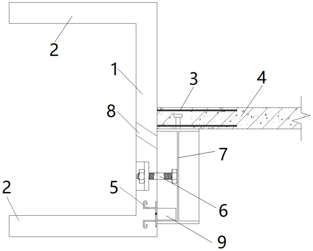
[0035] The prefabricated bay window provided in this embodiment includes: two prefabricated components arranged at intervals up and down, and a bay window space is formed between the two prefabricated components.

[0036] Such as figure 1 As shown, the prefabricated components include: a first prefabricated slab 1 and a second prefabricated slab 2 perpendicular to each other, the second prefabricated slab 2 has two parallel arrangements, and the two second prefabricated slabs 2 are spaced up and down Formed on the same side of the first prefabricated panel 1 . A plurality of first embedded parts 3 are pre-embedded in the middle of the first prefabricated panel 1, where the first embedded parts 3 are anchoring steel bars; the first embedded parts 3 have vertically protruding The protruding part on the outer surface is used to be embedded in the interior of the floor slab 4 . The first prefabricated panel 1 has a second embedded part 5 embedded along its width direction, and t...

Embodiment 2

[0040] The connection method of the prefabricated bay window provided in this embodiment includes the following steps:

[0041] S1: Before the concrete pouring of floor 4, hoist the prefabricated components of the upper floor and the prefabricated components of the lower floor to the corresponding installation positions respectively;

[0042] S2: The first embedded part 3 extends into the floor 4, and the positioning part 6 on the steel beam 7 penetrates into the positioning hole of the second prefabricated slab 2 to realize the preliminary positioning of the second prefabricated slab 2, the floor 4 and the steel beam 7 connect;

[0043] S3: between the second embedded part 5 and the steel beam 7 of the floor 4, welding is performed through the connecting block 9;

[0044] S4: pouring concrete into the grouting hole 8 to realize the pouring connection between the first prefabricated slab 1 and the steel beam 7;

[0045] S5: Co-casting the floor slab 4, the steel beam 7 and t...


PUM


Abstract

The invention provides a prefabricated bay window and a connecting method. The prefabricated bay window comprises two prefabricated parts which are arranged up and down in a spaced mode; a bay window space is formed between the two prefabricated parts; each prefabricated part is provided with a first prefabricated plate and a second prefabricated plate which are perpendicular to each other; the first prefabricated plates are used for being connected with a floor slab; the second prefabricated plates are used for extending outwards to enclose the bay window space; a first embedded part and a second embedded part which are arranged at an interval are arranged on each first prefabricated plate; each first embedded part is provided with an extending part suitable for being inserted into the floor slab; and the second embedded part is provided with a welding part suitable for being welded to a steel beam below the floor slab. The prefabricated parts are not cast in place, the two prefabricated parts are arranged up and down in a spaced mode, and the prefabricated parts are fixed to the floor slab and the steel beam through the first embedded parts and the second embedded parts. Compared with a cast-in-place reinforced concrete bay window, the bay window is short in construction period and high in efficiency; and the installation position can be adjusted at will, construction is flexible, and the phenomenon that the installation position is inaccurate is avoided.

Description

technical field [0001] The invention relates to the technical field of building construction, in particular to a prefabricated bay window and a connection method. Background technique [0002] In order to pursue the permeability of the architectural living room, form a wide viewing space, and improve the livable quality of urban residences, bay windows are widely used in residential projects as a special architectural design form. The upper and lower slabs of the bay window are generally cast-in-situ concrete cantilever structures, and the horizontal reinforcement of the cantilever slab is generally reserved or pre-embedded during wall construction. After the wall concrete is poured, the cantilever components are poured separately. [0003] The above-mentioned cast-in-place reinforced concrete bay window has a long pouring period and low construction efficiency; moreover, the pre-embedded horizontal steel bars of the cantilever slab are prone to inaccurate positions. Conte...

Claims


Application Information

Patent Timeline
IPC IPC(8): E04B1/00E04B1/38E04B1/41
CPCE04B1/00E04B1/38E04B1/41
Inventor 成能名陈韬黄钢黄航斌张瑜季泽华杨增华朱一层孟杰
Owner CHINA CONSTR STEEL STRUCTURE CORP LTD
Features
  • Generate Ideas
  • Intellectual Property
  • Life Sciences
  • Materials
  • Tech Scout
  • Unparalleled Data Quality
  • Higher Quality Content
  • 60% Fewer Hallucinations
Learn More