
An eye movement interaction method and device based on head timing signal correction

A timing signal and head movement technology, applied in the field of computer vision, can solve problems such as low accuracy, poor robustness, environmental brightness, and sensitivity to human eye opening and closing.

Active Publication Date: 2022-05-10
NAT INNOVATION INST OF DEFENSE TECH PLA ACAD OF MILITARY SCI
View PDF2 Cites 0 Cited by
  • Summary
  • Abstract
  • Description
  • Claims
  • Application Information

AI Technical Summary

Problems solved by technology

[0005] In view of this, the present invention provides an eye movement interaction method and device based on head timing signal correction, the main purpose of which is to solve the problems of traditional eye movement interaction methods by integrating human eye images, eye movement timing information and head movement timing information. It is sensitive to the brightness of the environment and the degree of opening and closing of human eyes, and has poor robustness and low accuracy in complex environments.

Method used


Image

  • An eye movement interaction method and device based on head timing signal correction
  • An eye movement interaction method and device based on head timing signal correction
  • An eye movement interaction method and device based on head timing signal correction

Examples


Embodiment 1

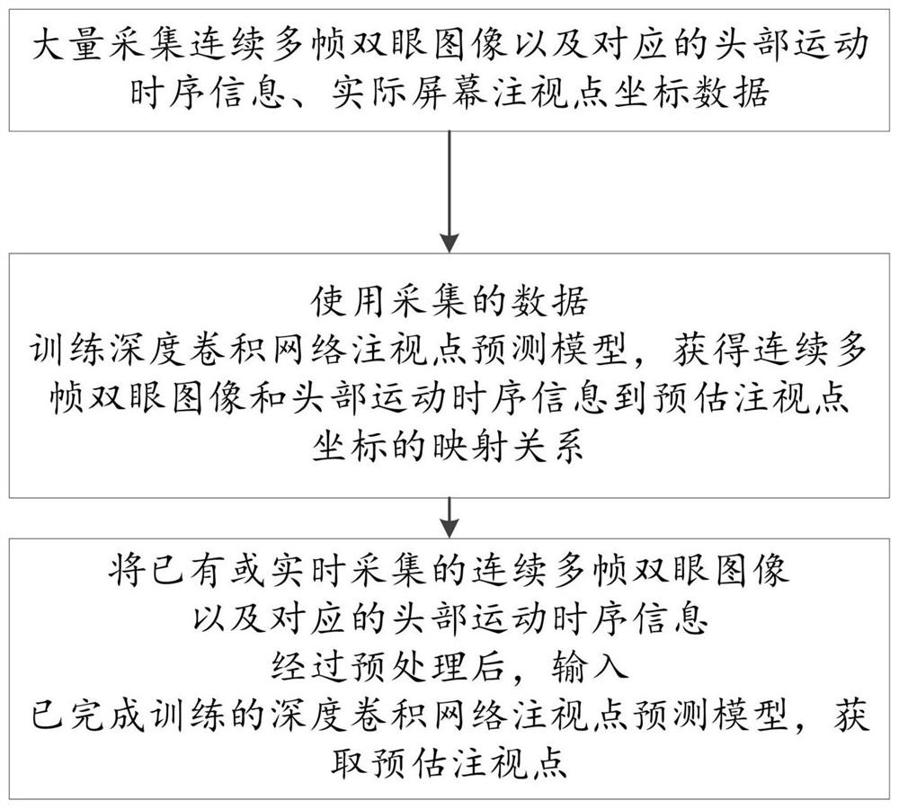
[0036] Please refer to figure 1 , which shows an overall flow chart of an eye movement interaction method based on head timing signal correction provided by an embodiment of the present invention.

[0037] Such as figure 1 As shown, the method of the embodiment of the present invention mainly includes the following steps:

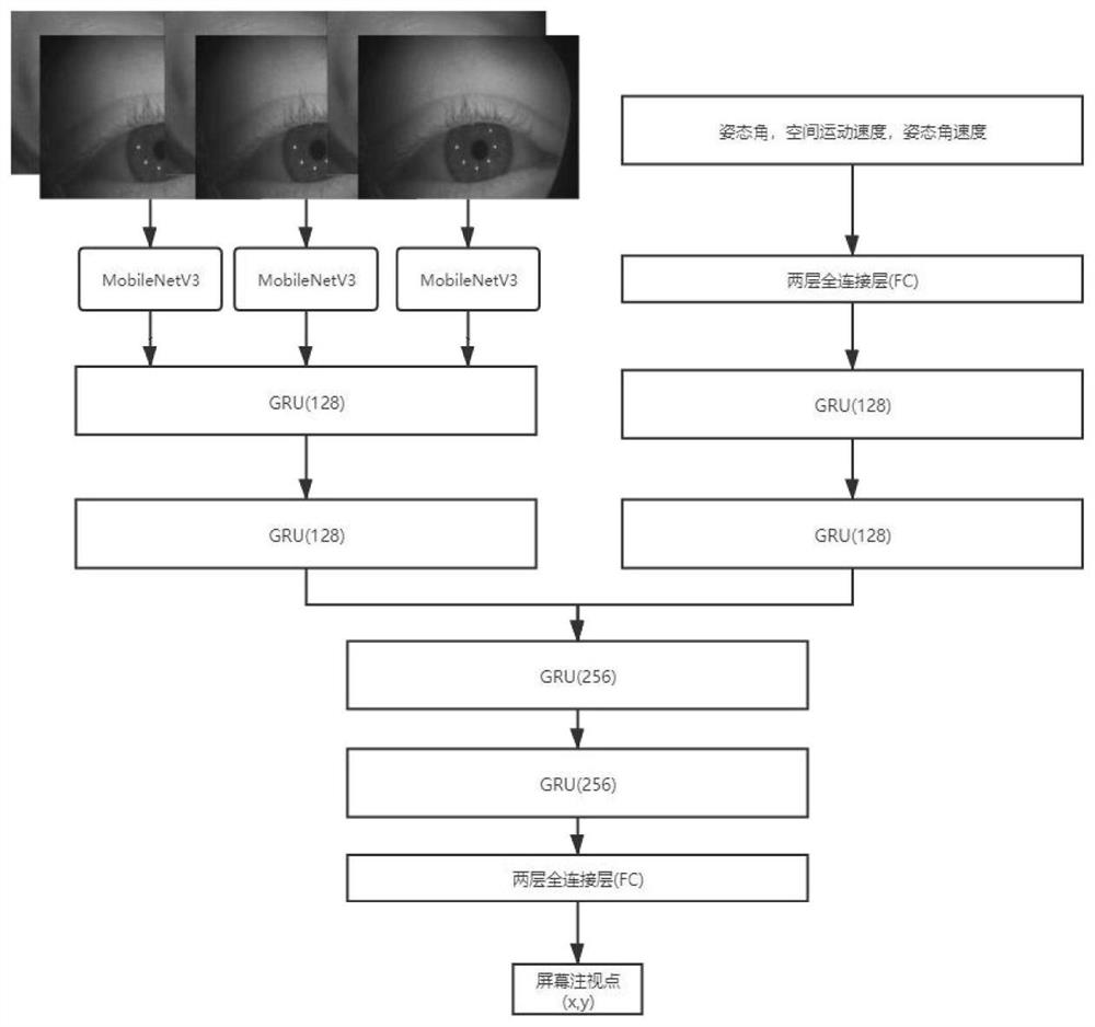
[0038] S1: Collect continuous multi-frame binocular images, corresponding head movement timing information, and actual screen gaze point coordinates as the first collected data; collect the first collected data of a large number of different people in different scenarios as the first collected data group, Perform preprocessing on the data in the first collection data group.

[0039] The binocular image data of the wearer is collected by the near-eye camera of the head-mounted device, and the binocular image is preprocessed into a 128*128 image. The corresponding binocular images in each frame are compressed successively and the mean and standard deviation...

Embodiment 2

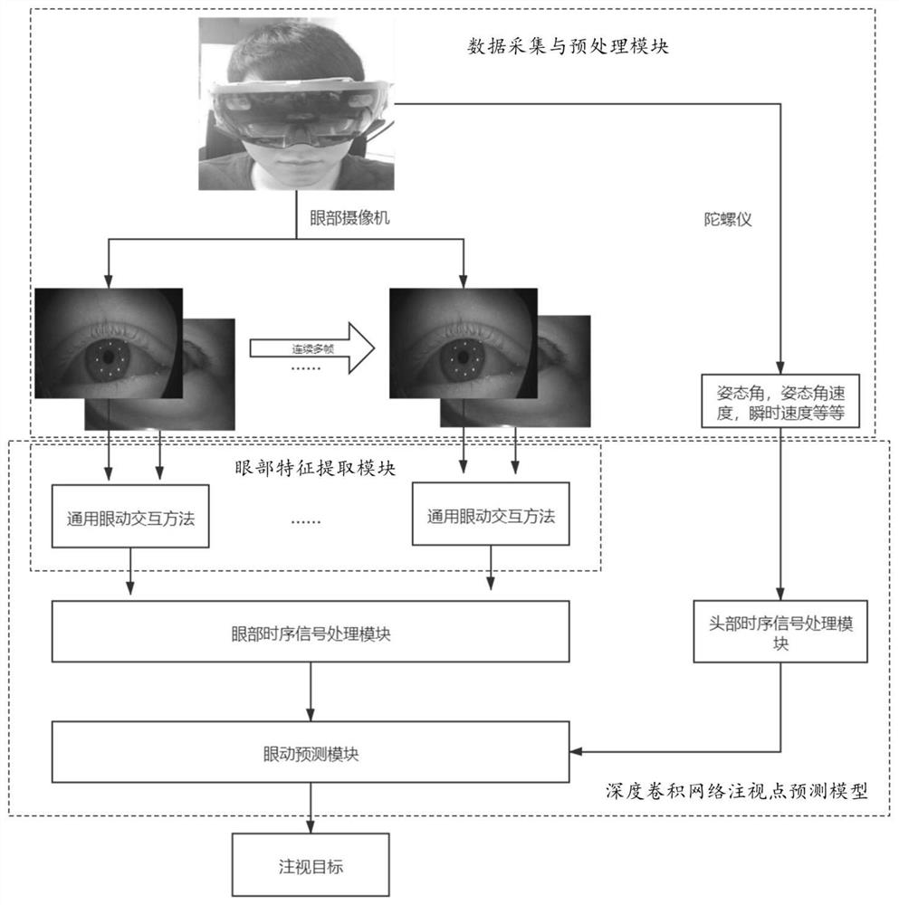
[0068] Furthermore, as an implementation of the methods shown in the above embodiments, another embodiment of the present invention also provides an eye movement interaction device based on head timing signal correction. This device embodiment corresponds to the foregoing method embodiment. For the convenience of reading, this device embodiment does not repeat the details in the foregoing method embodiment one by one, but it should be clear that the device in this embodiment can correspond to the foregoing method implementation. Everything in the example. image 3 A block diagram of an eye movement interaction device based on head timing signal correction provided by an embodiment of the present invention is shown. Such as image 3 As shown, in the device of this embodiment, there are following modules:

[0069] 1. Data collection and preprocessing module: collect continuous multi-frame binocular images and corresponding head movement timing information, and actual screen ga...


PUM


Abstract

The invention discloses an eye movement interaction method and device based on head timing signal correction, belonging to the technical field of computer vision. The method includes: collecting a large number of continuous multi-frame binocular images and corresponding head movement timing information, actual screen gaze point coordinates, and preprocessing the collected data; using the collected large amount of data to train the gaze point of a deep convolutional network The prediction model obtains the mapping relationship between continuous multi-frame binocular images and head movement timing information to the estimated fixation point coordinates; the existing or real-time collected data is input into the trained deep convolutional network fixation point prediction model to obtain the estimated fixation point point. The invention fuses head timing signals and eye image timing signals, and uses the powerful feature processing capability of deep learning to accurately and quickly estimate the gaze point of the human eye; through pre-training the gaze point prediction model of the deep convolution network, new users do not need to correct it when using it , you can directly wear the head-mounted eye tracker for real-time eye movement interaction.

Description

technical field [0001] The present invention relates to the technical field of computer vision, in particular to an eye movement interaction method and device based on head timing signal correction. Background technique [0002] Eye movement interaction technology is to track the state of human eye gaze direction through various methods such as eye electrical signals, optical signals, and picture signals, and then use this method to conduct human-computer interaction. It has a huge role in future human-computer interaction. application potential. External devices capable of input and output and corresponding software, namely keyboards, mice, and various pattern recognition devices can complete traditional human-computer interaction, but traditional human-computer interaction is mostly manual operation, sometimes with voice operation, which has certain For example, for disabled persons with inconvenient upper limbs or pilots in military battles, traditional human-computer in...

Claims


Application Information

Patent Timeline
Patent Type & Authority Patents(China)
IPC IPC(8): G06F3/01G06V40/18G06V40/20G06K9/62G06N3/04G06N3/08
CPCG06F3/013G06F3/012G06N3/084G06N3/08G06N3/045G06F18/253
Inventor 张敬王小东闫野印二威谢良闫慧炯罗治国艾勇保张亚坤
Owner NAT INNOVATION INST OF DEFENSE TECH PLA ACAD OF MILITARY SCI
Learn More