Emulsified feed feeding system device
A system device, feed technology, applied in feed, mixer with rotary stirring device, chemical instrument and method, etc., can solve problems such as uneven feeding, eliminate quality differences, improve mixing effect, and improve feeding The effect of precision
- Summary
- Abstract
- Description
- Claims
- Application Information
AI Technical Summary
Problems solved by technology
Method used
Image
Examples
Embodiment 1
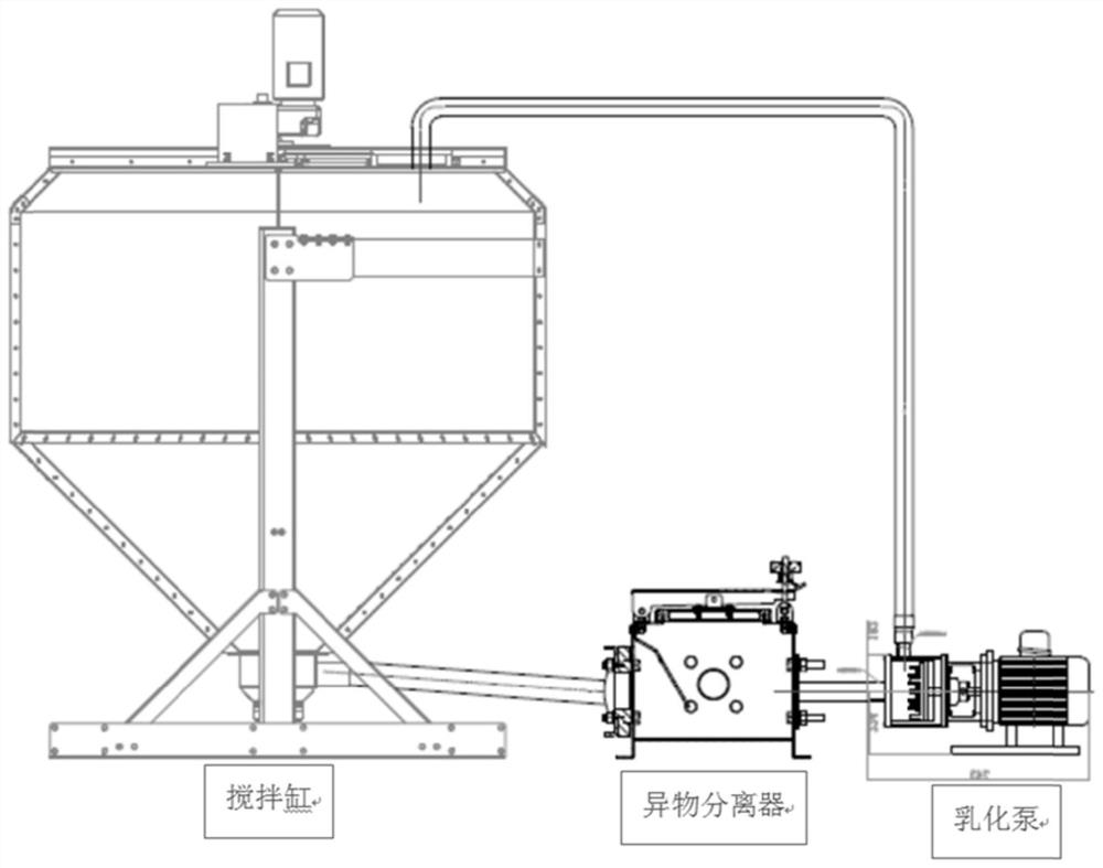
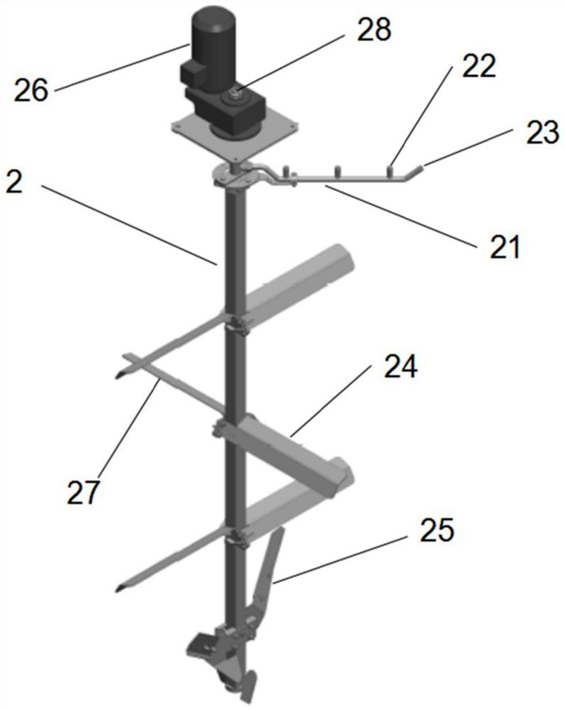
[0025] like Figure 1-2 As shown, it includes a mixing tank, the bottom of the mixing tank is connected with a foreign matter separator, the foreign matter separator is connected with an emulsification pump, the emulsification pump is connected to the mixing tank through a pipeline, a support frame is provided at the lower end of the mixing tank, and a Stirring shaft 2, the stirring shaft is provided with a cleaning pipe 21, the cleaning pipe 21 is provided with a vertical cleaning nozzle 22 and an inclined cleaning nozzle 23, the stirring shaft 2 is provided with a stirring paddle 24 and a crushing paddle 27, and the stirring shaft 2 lower end is provided with The stirring paddle 25 at the bottom, the upper end of the stirring shaft 2 is provided with a rotary interface 28, the rotating interface 28 is matched with a rotary joint, the upper end of the stirring shaft 2 is provided with a stirring motor 26, the stirring motor 26 is arranged on the top of the mixing cylinder, and...
Embodiment 2
[0031] On the basis of Example 1, a steel mixing tube is installed at the bottom of the mixing tank by welding or screwing, the upper end of the mixing tube communicates with the bottom of the mixing tank, and the lower end of the mixing tube is fixedly connected with a first liquid inlet pipe and a second liquid inlet pipe. Mixing baffles are welded in the mixing tube, and the mixing baffles are arranged staggeredly. The nozzles of the first liquid inlet pipe and the second liquid inlet pipe are arranged oppositely. The bottom is also welded or screwed to be provided with a vertical blowing pipe, and the top of the mixing tank is also welded or screwed to be provided with a vent pipe, and an activated carbon filter layer is arranged in the vent pipe, and a glass transparent window is also provided on the stirring tank.
[0032] When the mixing tank starts to work, the two liquid materials enter the mixing tube from the first liquid inlet pipe and the second liquid inlet pipe r...
Embodiment 3
[0035] On the basis of Example 2, further optimization is made. On the basis of Example 2, the first liquid inlet pipe and the second liquid inlet pipe are provided with a liquid inlet pump, and the first liquid inlet pipe and the second liquid inlet pipe are provided with There is a valve, the liquid outlet pipe is provided with a valve, and the air blowing pipe is provided with a valve.
[0036] In this embodiment, the flow rate of the liquid can be accelerated through the liquid inlet pump to further enhance the mixing effect, and the valve control is more convenient, safe and reliable.
PUM
 Abstract
Description
Claims
Application Information
 - R&D
- Intellectual Property
- Life Sciences
- Materials
- Tech Scout
- Unparalleled Data Quality
- Higher Quality Content
- 60% Fewer Hallucinations
Browse by: Latest US Patents, China's latest patents, Technical Efficacy Thesaurus, Application Domain, Technology Topic, Popular Technical Reports.
© 2025 PatSnap. All rights reserved.Legal|Privacy policy|Modern Slavery Act Transparency Statement|Sitemap|About US| Contact US: help@patsnap.com


