Conveyor belt tensioning device and belt conveyor

A belt conveyor and tensioning device technology, applied in conveyors, conveyor objects, conveyor control devices, etc., can solve problems such as shortening the service life of stressed components, affecting material conveying efficiency, and improving equipment durability. , to meet the normal operation, the effect of low price

Pending Publication Date: 2021-09-24
HUANENG POWER INTERNATIONAL
View PDF8 Cites 0 Cited by
  • Summary
  • Abstract
  • Description
  • Claims
  • Application Information

AI Technical Summary

Problems solved by technology

Greatly affect the efficiency of material transportation
[0007] In the belt conveyor that actually uses the screw tensioning device, the method of over-tensioning the conveyor belt is always used to offset the elongation of the conveyor belt when the belt conveyor is running, especially when it is started. This method makes the belt conveyor All kinds of stress-bearing parts of the conveyor are subjected to a large pulling force of the conveyor belt, which also leads to a significant shortening of the service life of these stress-bearing parts

Method used


Image

  • Conveyor belt tensioning device and belt conveyor
  • Conveyor belt tensioning device and belt conveyor
  • Conveyor belt tensioning device and belt conveyor

Examples


Embodiment 1

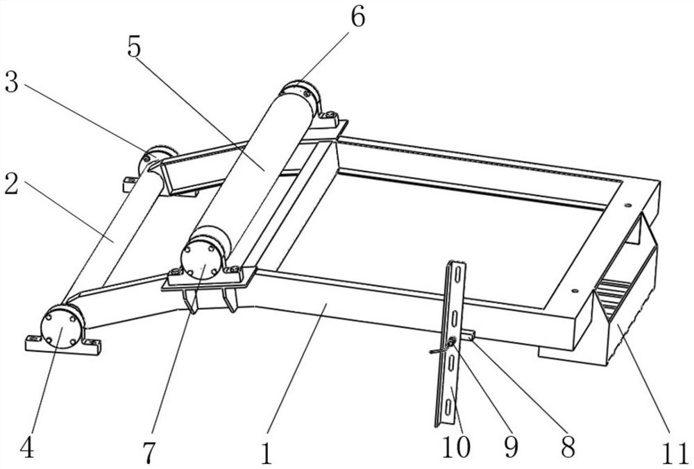
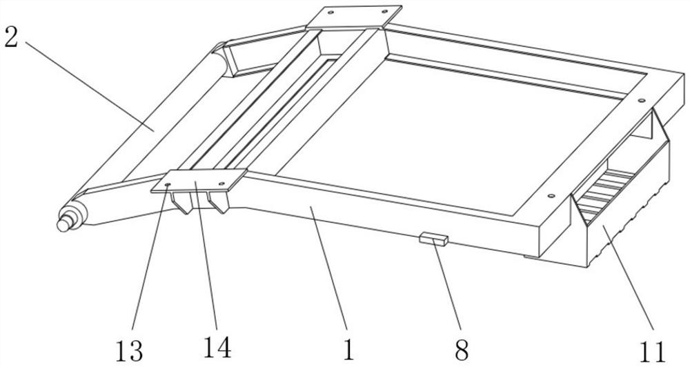
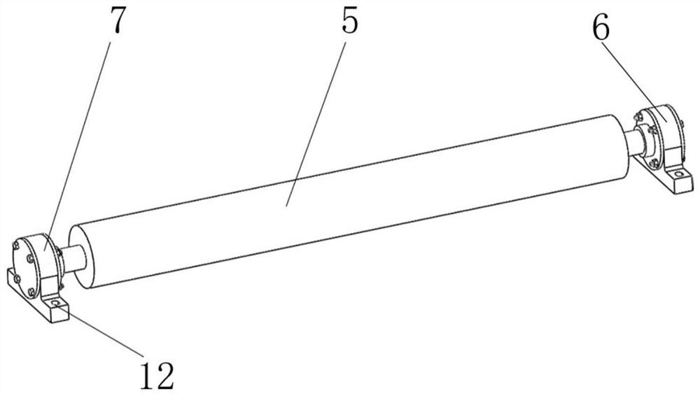
[0037] A conveyor belt tensioner for tensioning the conveyor belt of a belt conveyor such as Figure 1~4 As shown, it includes a rotating assembly, a main frame 1, a conveyor belt pressing assembly, a weight assembly, and a sensor assembly. The rotating assembly is installed on one end of the main frame 1, and the weight assembly is installed on the other end of the main frame 1. The conveyor belt pressing assembly is arranged on the middle top surface of the main frame 1 . When in use, the conveyor belt tensioning device is set on the belt conveyor, the main frame 1 is rotatably connected with the frame of the belt conveyor through the rotating assembly, and the return part of the conveyor belt of the belt conveyor passes through the conveyor belt and is compressed Components, the hammer component drives the main frame 1 and the conveyor belt pressing component to press down to complete the self-adaptive tensioning of the conveyor belt, adjust the tension of the conveyor belt...

Embodiment 2

[0046] A belt conveyor, including a conveyor belt tensioning device described in Embodiment 1, the conveyor belt tensioning device is rotatably connected to the frame of the belt conveyor through a rotating assembly, and the conveyor belt of the belt conveyor The return part of the belt passes through the conveyor belt compression assembly, and the weight assembly drives the main frame 1 to rotate and drives the conveyor belt compression assembly to press and tension the conveyor belt.

[0047] Specifically, the present invention can be set at the return part of the conveyor belt of the belt conveyor. As in this embodiment, the conveyor belt tensioning device is arranged at the rear of the driving roller of the belt conveyor to tighten the transmission. The elongation of the conveyor belt when the roller is dragging the conveyor belt.

[0048] In this example, if Figure 7 Shown is an existing belt conveyor structure, which includes a head drop coal hopper 18 set at the head,...


PUM


Abstract

The invention relates to a conveyor belt tensioning device and a belt conveyor. The conveyor belt tensioning device is used for tensioning a conveyor belt of the belt conveyor, the conveyor belt tensioning device comprises a rotating assembly, a main frame, a conveyor belt pressing assembly and a heavy hammer assembly, the rotating assembly is installed at one end of the main frame, the heavy hammer assembly is installed at the other end of the main frame, and the conveyor belt pressing assembly is arranged on the top face of the middle of the main frame. Compared with the prior art, self-adaptive continuous tensioning of the conveyor belt is achieved, the structure is simple, the device is safe and reliable, and the requirement for long-term stable operation of the belt conveyor can be met.

Description

technical field [0001] The invention relates to the field of belt conveyors, in particular to a conveyor belt tensioning device and a belt conveyor. Background technique [0002] Belt conveyor is a common equipment for industrial transportation of bulk materials. The conveyor belt of the belt conveyor needs to be tensioned by a special tensioning device, so that the conveyor belt has sufficient pressure between the driving roller and each redirecting roller. Generate enough friction to meet the needs of transmission, and also meet the needs of the conveyor belt to transport materials. [0003] The elongation (elastic elongation and permanent elongation) of the conveyor belt produced according to the national standard is within a certain range, that is, the extension of the conveyor belt per unit length under normal operation or after a period of use quantity. The belt conveyor adopts a special tensioning device to tension the conveyor belt to meet the tension required for ...

Claims


Application Information

Patent Timeline
Patent Type & Authority Applications(China)
IPC IPC(8): B65G23/44B65G43/00
CPCB65G23/44B65G43/00
Inventor 张晓
Owner HUANENG POWER INTERNATIONAL
Why Eureka
Try Eureka