Anti-interference electricity module in bypass mode and control method of anti-interference electricity module

A bypass mode and anti-sway technology, which is applied in the field of anti-sway module and its control, can solve the problems of easy-to-burn contactor coils and device components, tripping and shutdown, and easy-to-burn device components, etc., to meet long-term stable operation , high reliability, small size effect

Active Publication Date: 2014-02-05
ZHUHAI WANLIDA ELECTRICAL AUTOMATION
View PDF5 Cites 20 Cited by
  • Summary
  • Abstract
  • Description
  • Claims
  • Application Information

AI Technical Summary

Problems solved by technology

[0010] (2) Causes of tripping and shutdown caused by "shock electricity"
[0012] (3) The impact of shaking electricity on the motor of the power supply circuit
[0016] 1. Starting method: pulsating DC starting contactor is easy to burn out the contactor coil and device components; when pulsating DC starting contactor, when using a large-capacity contactor, the internal resistance of the contactor is very small (2 to 10 ohms); ( 1) It is easy to burn out the contactor: because the internal resistance of the contactor is small, the current through the contactor coil is very large (tens of amperes) under the condition of constant pulsating DC voltage, which makes the contactor coil easy to damage; (2) easy to burn Device device: Because the device itself switches the higher pulsating DC to the DC voltage provided by the switching power supply by controlling the electromagnetic relay, the large current flows through the electromagnetic relay of the device; in this case, the control circuit part of the device The device is easy to burn out
[0017] 2. The principle of the control part: the control part is easy to burn out the contacts of the electromagnetic relay and the internal circuit board of the device, thereby reducing the service life of the device; (1) Because the device uses an electromagnetic relay, most electromagnetic relay contacts have a DC capacity of on and off Not high, when the DC current flows through the electromagnetic relay contact greater than the rated value of the electromagnetic relay, the electromagnetic relay contact will appear "arcing" when it is released, so the electromagnetic relay contact often burns out, which may sometimes cause the electromagnetic relay to catch fire. Seriously, it will lead to fire; (2) If the electromagnetic relay burns out due to "arcing", there are two possibilities for the contacts of the electromagnetic relay. Dead on the same side (normally open or normally closed), the second possibility is: the contact of the electromagnetic relay connected to the live wire is "sticky" on the normally open side and the contact of the electromagnetic relay connected to the neutral line is "sticky" to the normally closed side. Or the contact of the electromagnetic relay connected to the live wire is "sticky" on the normally closed side and the contact of the electromagnetic relay connected to the neutral line is "sticky" to the normally open side; when the first case occurs, it only affects the device and cannot control the switching action, resulting in The anti-shaking function of the device fails; when the second situation occurs, the AC power and the DC power provided by the switching power supply are short together, which leads to circuit board burnout, device burnout, power supply circuit protection tripping, etc.

Method used


Image

  • Anti-interference electricity module in bypass mode and control method of anti-interference electricity module
  • Anti-interference electricity module in bypass mode and control method of anti-interference electricity module

Examples


Embodiment Construction

[0039] In order to make the object, technical solution and advantages of the present invention clearer, the present invention will be further described in detail below in conjunction with the accompanying drawings and embodiments. It should be understood that the specific embodiments described here are only used to explain the present invention, not to limit the present invention.

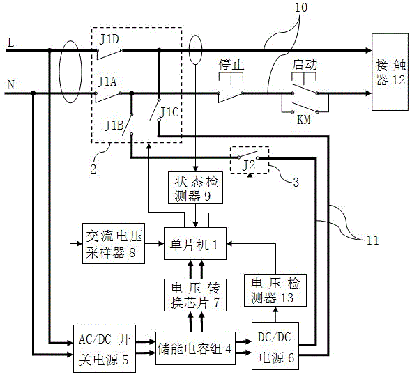
[0040] Such as figure 1 as shown in:

[0041] An anti-sway electricity module using a bypass mode described in the embodiment of the present invention is an anti-sway electricity module in an offline mode, including a single-chip microcomputer 1, an electromagnetic relay 2, a solid-state relay 3, an energy storage capacitor group 4, and an AC / DC switch Power supply 5 , DC / DC power supply 6 , voltage conversion chip 7 , AC voltage sampler 8 and state detector 9 . Wherein, the input end and the output end of the AC / DC switching power supply 5 are respectively electrically connected to the power gri...


PUM


Abstract

The invention relates to an anti-interference electricity module in a bypass mode and a control method of the anti-interference electricity module. The anti-interference electricity module comprises a single-chip microcomputer, an electromagnetic relay, a solid-state relay, an energy storage capacitor set, an AC/DC switching power supply, a DC/DC power supply, a voltage conversion chip, an alternating voltage sampler and a state detector, wherein two ends of the alternating voltage sampler and two ends of the state detector are respectively in signal connection with a grid and the single-chip microcomputer. The input end and the output end of the AC/DC switching power supply are respectively and electrically connected with the grid and the energy storage capacitor set, and the output end of the energy storage capacitor set is electrically connected with the single-chip microcomputer and a contactor respectively through the voltage conversion chip and the DC/DC power supply. A normally closed contact of the electromagnetic relay is arranged on the grid, and a normally open contact of the electromagnetic relay and a normally open contact of the solid-state relay are connected in series on a direct current power supply loop. The anti-interference electricity module can supply alternating current and direct current to the contactor respectively in the normal running process and the electricity interference process, the defects of starting of pulsating direct current are overcome, and pull-in of the contactor is maintained, so the reliability is high and operational requirements of a continuous production line can be met.

Description

technical field [0001] The invention belongs to the technical field of anti-sway electricity in electric power systems, and in particular relates to an anti-sway electricity module and its Control Method. Background technique [0002] During the operation of the power system, due to lightning strikes, short-circuit to ground, fault reclosing, backup self-switching, external and internal power grid faults, large-scale equipment start-up, etc., the power grid faults caused by them will cause large instantaneous voltage fluctuations. Or short-term power failure and recovery, this phenomenon is called "shake power". [0003] There are mainly the following situations: [0004] (1) The voltage dips and rises for a duration of 0.5 cycle to 1 min, and the voltage rises to 110-180% of the nominal voltage or drops to 10-90% of the nominal voltage. [0005] (2) Voltage flicker, the voltage waveform envelope shows a regular change or a series of random changes in the voltage amplitud...

Claims


Application Information

Patent Timeline
Patent Type & Authority Applications(China)
IPC IPC(8): H02H1/06
Inventor 朱志伟李山德全柯乔朱云垣邹蕾
Owner ZHUHAI WANLIDA ELECTRICAL AUTOMATION
Why Eureka
Try Eureka