Slope reinforcing structure for civil engineering

A technology for strengthening structures and civil engineering. It is applied in basic structure engineering, waterway system, sewer system, etc. It can solve problems such as soil and rock blocking, and achieve the effect of improving firmness, improving flexibility, and reducing the risk of soil and rock landslides.

Inactive Publication Date: 2021-09-24
LUSHAN COLLEGE OF GUANGXI UNIV OF SCI & TECH
View PDF0 Cites 0 Cited by
  • Summary
  • Abstract
  • Description
  • Claims
  • Application Information

AI Technical Summary

Problems solved by technology

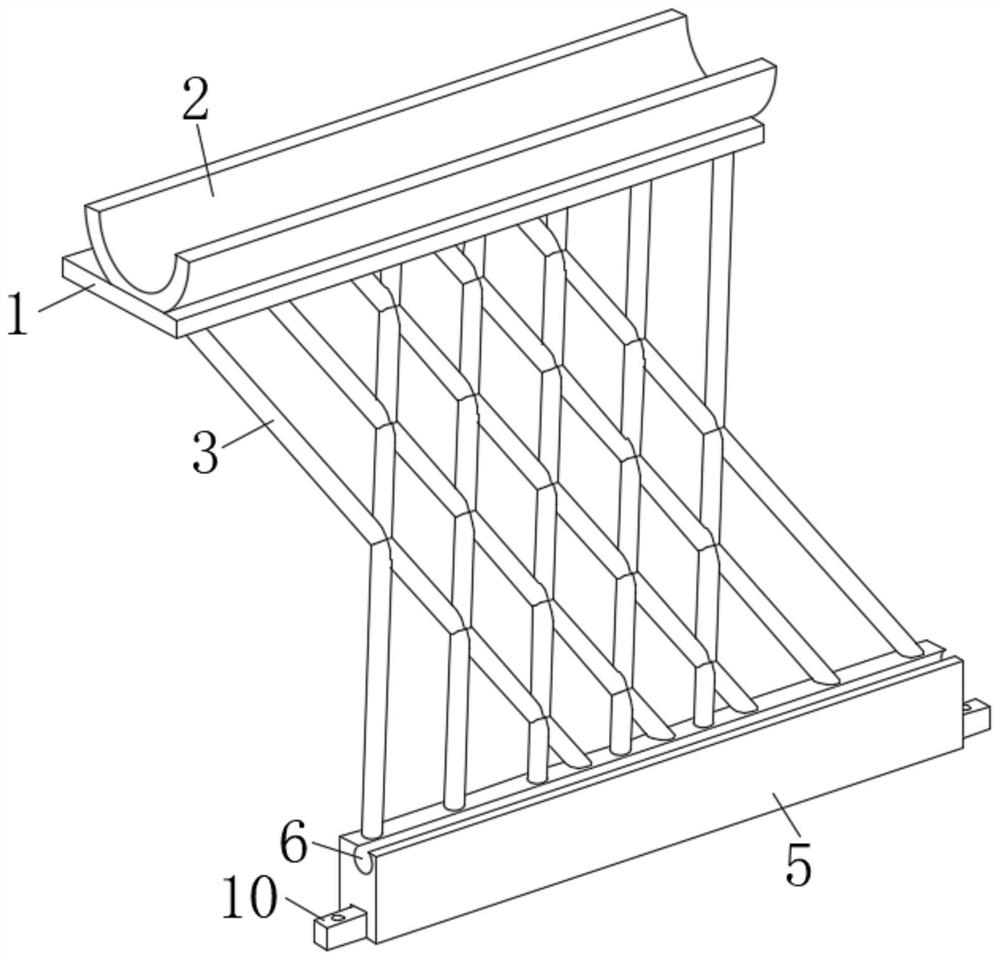
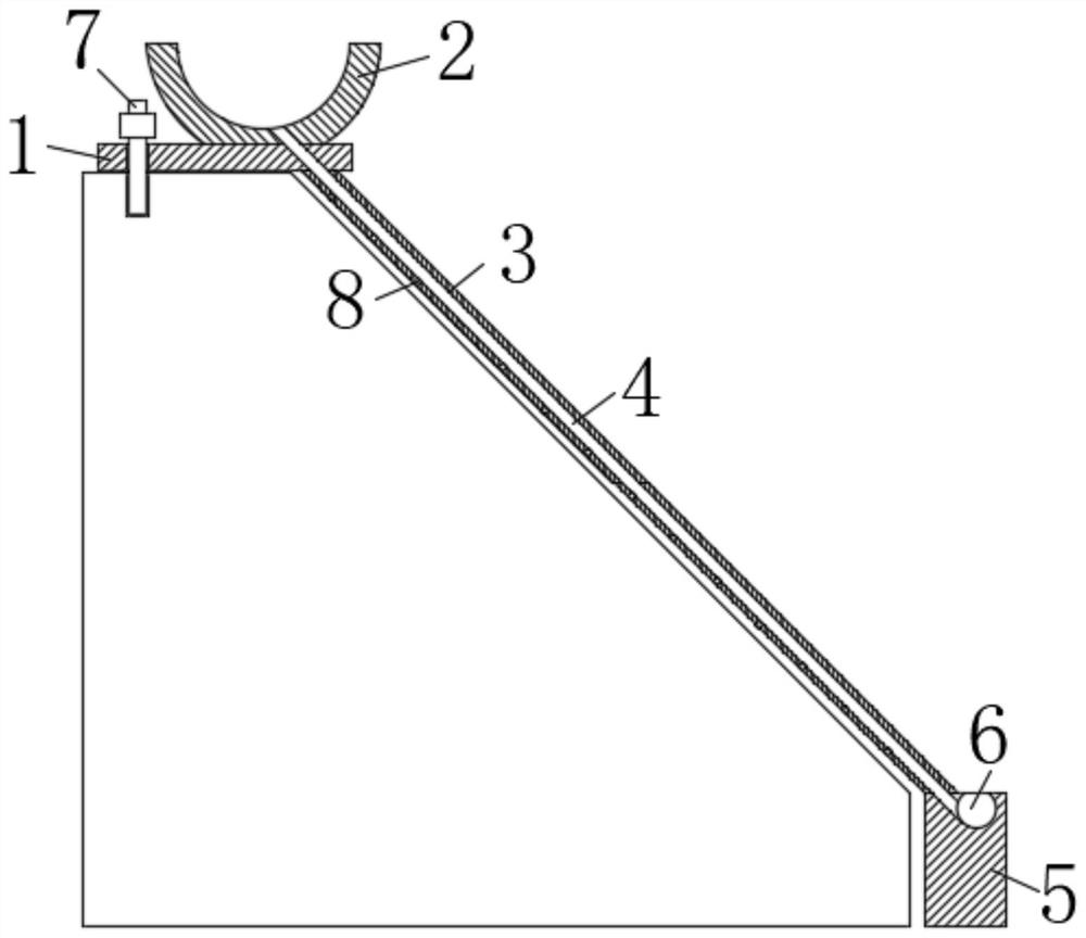
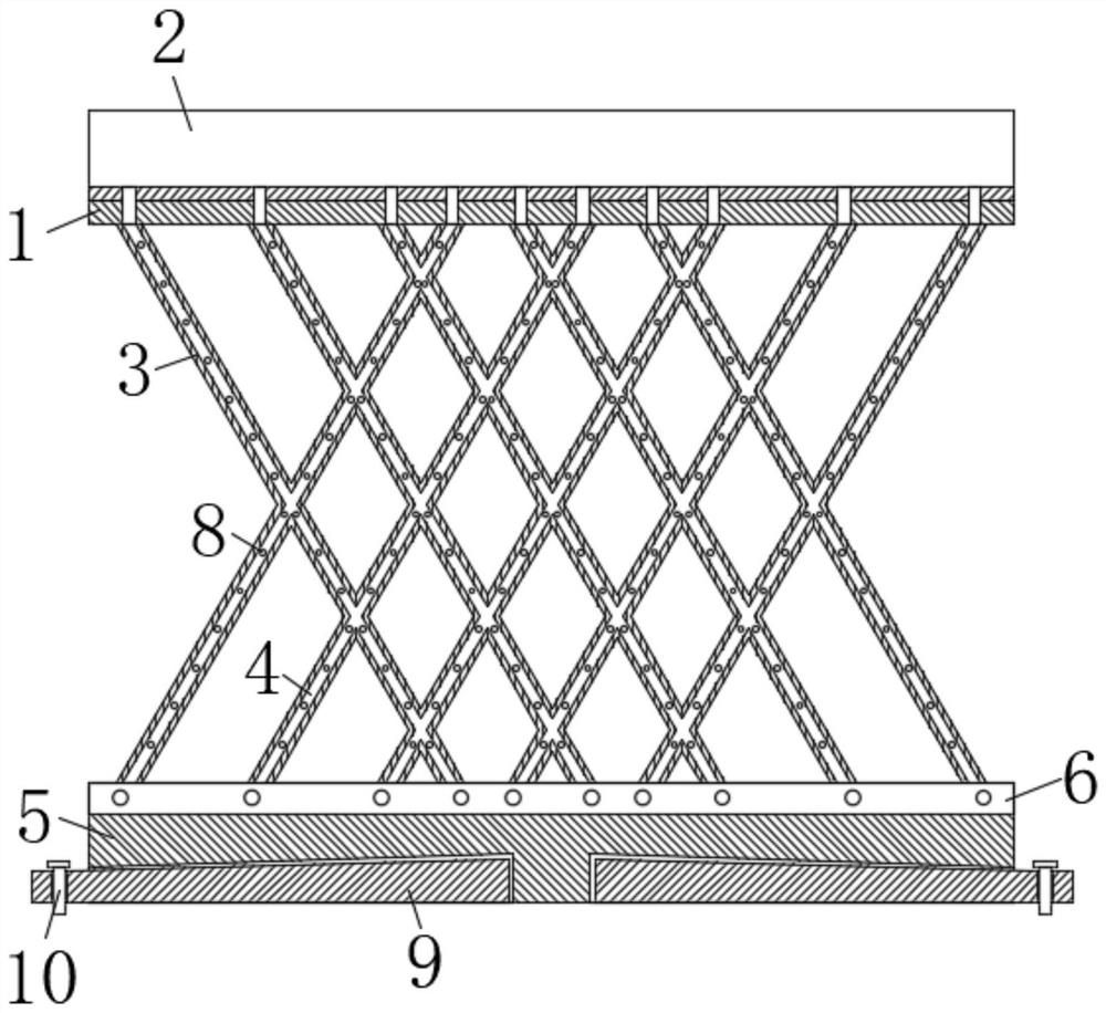
[0003] The purpose of the present invention is to solve the existing method of reinforcing the slope, which usually uses steel wire mesh or cement to cover the earth and rocks below, but in this way, when it encounters rainy weather, the rain will still remove the earth and rocks in the soil. However, a slope reinforcement structure for civil engineering is proposed, which can be staggered in the vacant space reserved by the protective fence when the slope is reinforced. For planting, when it encounters rainy weather, the water collecting plate at the upper end of the slope will collect the rainwater, and discharge it into the drainage groove on the positioning block at the bottom of the slope through the flow groove in the protective fence, and then drain the rainwater through the drainage groove Walk, when the rainwater passes through the gutter, it can also pass through the drainage holes to irrigate the roots of the vegetation, which is conducive to the growth of the vegetation. Under the action of the fence and vegetation, the rainwater can be effectively treated, effectively improving the The stability of the slope reduces the risk of landslides

Method used


Image

  • Slope reinforcing structure for civil engineering
  • Slope reinforcing structure for civil engineering
  • Slope reinforcing structure for civil engineering

Examples


Embodiment Construction

[0018] The following will clearly and completely describe the technical solutions in the embodiments of the present invention with reference to the accompanying drawings in the embodiments of the present invention. Obviously, the described embodiments are only some, not all, embodiments of the present invention. Based on the embodiments of the present invention, all other embodiments obtained by persons of ordinary skill in the art without making creative efforts belong to the protection scope of the present invention.

[0019] In the description of the present invention, it should be noted that the terms used herein are only used for the purpose of describing specific embodiments, and are not intended to limit the present invention. As used herein, the singular forms "a", "an", and "the" are intended to include the plural forms as well, unless the context clearly dictates otherwise. When terms such as "comprising" and / or "comprising" are used, it is intended to state that the...


PUM


Abstract

The invention discloses a slope reinforcing structure for civil engineering. The slope reinforcing structure for civil engineering comprises a fixing plate arranged at the upper end of a slope, a water collecting plate is fixedly connected to the side wall of one side of the upper end of the fixing plate, the water collecting plate is arranged in a U shape, a fixing mechanism is arranged on the other side of the fixing plate, a plurality of protective fences are fixedly connected to the bottom end of the fixing plate, water flowing grooves are formed in the side walls of the protective fences, the bottom ends of the protective fences are fixedly connected with the same positioning block, a drainage groove is formed in the side wall of the upper end of the positioning block, and the positioning block is provided with a lifting mechanism. When the slope is reinforced, planting is carried out in the vacant positions reserved in the staggered mode of the protective fences, rainwater is drained into the drainage groove in the positioning block at the bottom end of the slope through the water flowing grooves in the protective fences in rainy days, then the rainwater is drained away through the drainage groove, the roots of vegetation can be irrigated, under the action of the protective fences and the vegetation, rainwater can be effectively treated, the firmness of the slope is effectively improved, and the danger of earth-rock landslide is reduced.

Description

technical field [0001] The invention relates to the technical field of civil engineering, in particular to a slope reinforcement structure for civil engineering. Background technique [0002] Nowadays, with the continuous development of society, a large amount of land has been developed. When excavating the road surface, the soil and rocks on both sides of the road surface will be exposed, which will not only destroy the structure of the land, but also destroy the vegetation in the land. . Moreover, the soil and rocks exposed to the outside world are prone to fall when they are washed by strong rainwater, causing serious water and soil erosion, which not only cannot ensure the stability of the slope, but also destroys the ecology. Therefore, during construction, the side slope will be reinforced, not only using external tools to block it, but also planting a large number of vegetation on the side slope, using the roots of the vegetation. The existing method of strengthenin...

Claims


Application Information

Patent Timeline
Patent Type & Authority Applications(China)
IPC IPC(8): E02D17/20E03F3/02E03F3/04E02D5/74
CPCE02D17/20E03F3/02E03F3/04E03F3/046E02D5/74
Inventor 张娜郭桢覃媛媛尹佳吴长清
Owner LUSHAN COLLEGE OF GUANGXI UNIV OF SCI & TECH
Why Eureka
Try Eureka