A safe anti-seismic multi-layer buffer building structure
A building structure and safety technology, applied in building components, building structures, buildings, etc., can solve problems such as building damage, fatal injuries to people in the house, and easy bending of columns, and achieve the effect of supporting and buffering.
- Summary
- Abstract
- Description
- Claims
- Application Information
AI Technical Summary
Problems solved by technology
Method used
Image
Examples
Embodiment 1
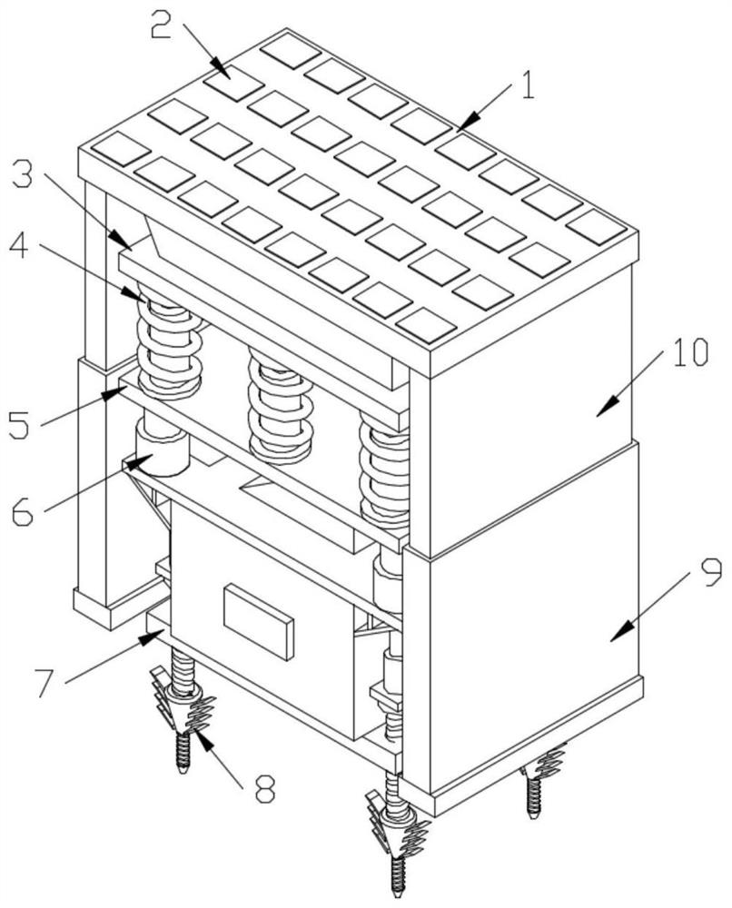
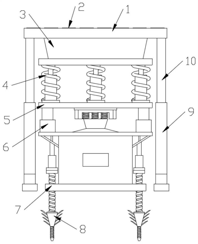
[0028] Example one, by Figure 1-2 Provide, a kind of safety earthquake-resistant multi-layer buffer building structure of the present invention, comprises a fixed base plate 7, the position around the top of the fixed base plate 7 is connected with a grounding assembly 8 by screws, and the top of the fixed base plate 7 is fixedly connected with a buffer stabilization assembly 6, A bearing plate 5 is fixedly connected to the end of the buffer stabilization component 6 facing away from the fixed bottom plate 7 , and the end of the bearing plate 5 opposite to the buffer stabilization component 6 is fixedly connected to a uniformly distributed hydraulic shock absorber 4 , and the top of the hydraulic shock absorber 4 is fixedly connected. There is a force-bearing component 3, the top of the force-bearing component 3 is fixedly connected to a force-bearing plate 1, the top of the force-bearing plate 1 is fixedly connected to the evenly distributed frosted buffer pads 2, and the bot...
Embodiment 2
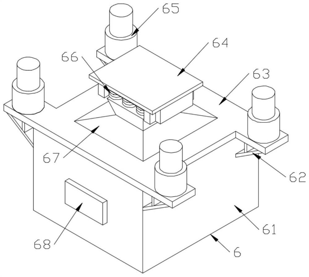
[0029] Embodiment 2, on the basis of Embodiment 1, according to Figure 3-5 , the buffer and stability assembly 6 includes a buffer force block 61, an auxiliary support plate 62, a top plate 63, a connecting base 64, a spring sleeve 65, a shock-absorbing spring 66, a buffer assembly 67, a limit plate 68 and a shock-absorbing spring 2 69 , wherein the buffer force-bearing block 61 is fixedly connected to the limit plate 68 at the front end, and the top end of the buffer force-bearing block 61 is fixedly connected to the top plate 63, and the bottom end of the top plate 63 is fixedly connected to the auxiliary support plate 62. The spring sleeve 65 is fixedly connected at the positions around the top end, the top end of the top plate 63 is plugged into the movable connection buffer assembly 67, the top end of the buffer assembly 67 is fixedly connected to the evenly distributed shock-absorbing spring 1 66, and the shock-absorbing spring 1 66 is in phase with the buffer assembly 6...
Embodiment 3
[0031] Embodiment 3, on the basis of Embodiments 1 and 2, according to Image 6 , the grounding assembly 8 includes a connecting plate 81, a connecting rod 82, a hollow sleeve 83, a fixed screw 84, a barb 85, a connecting ring 86 and a threaded rod 87, wherein the top of the connecting plate 81 is fixedly connected to the hollow sleeve 83. The top end of the sleeve 83 is plugged into the movable connection connecting rod 82 , a fixed screw 84 is arranged below the connecting plate 81 , the bottom end of the fixed screw 84 is fixedly connected to the connecting ring 86 , and the outer surface of the connecting ring 86 is fixedly connected to the two vertically distributed A set of barbs 85 is formed, and the connecting ring 86 is fixedly connected with a threaded rod 87 at one end opposite to the fixing screw 84 .
[0032] working principle:
[0033]In the specific implementation, the frosted buffer pad 2 and the force-bearing plate 1 are subjected to the pressure from above. ...
PUM
 Abstract
Description
Claims
Application Information
 - R&D
- Intellectual Property
- Life Sciences
- Materials
- Tech Scout
- Unparalleled Data Quality
- Higher Quality Content
- 60% Fewer Hallucinations
Browse by: Latest US Patents, China's latest patents, Technical Efficacy Thesaurus, Application Domain, Technology Topic, Popular Technical Reports.
© 2025 PatSnap. All rights reserved.Legal|Privacy policy|Modern Slavery Act Transparency Statement|Sitemap|About US| Contact US: help@patsnap.com


