
Fabricated double-layer corrugated steel plate composite shear wall and splicing method thereof

A corrugated steel plate and shear wall technology, applied in protective buildings/shelters, building types, buildings, etc., can solve the problems of low construction efficiency, inconvenient construction, and complicated operation, and achieve enhanced connection strength and construction efficiency. High, easy-to-use effects

Active Publication Date: 2021-09-24
CHONGQING UNIV
View PDF28 Cites 2 Cited by
  • Summary
  • Abstract
  • Description
  • Claims
  • Application Information

AI Technical Summary

Problems solved by technology

[0006] In view of this, the present invention solves the problem of poor integrity of the assembled shear wall and prefabricated floor in the connection mode between the existing prefabricated shear wall and the shear wall and the shear wall and the prefabricated floor. Multiple splicing, cumbersome operation and low construction efficiency seriously restrict the promotion of prefabricated shear wall structures. To provide a prefabricated double-layer corrugated steel composite shear wall and its splicing method

Method used


Image

  • Fabricated double-layer corrugated steel plate composite shear wall and splicing method thereof
  • Fabricated double-layer corrugated steel plate composite shear wall and splicing method thereof
  • Fabricated double-layer corrugated steel plate composite shear wall and splicing method thereof

Examples


Embodiment 1

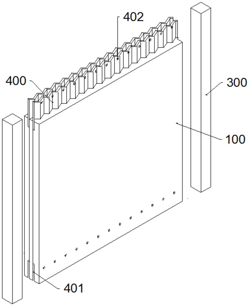
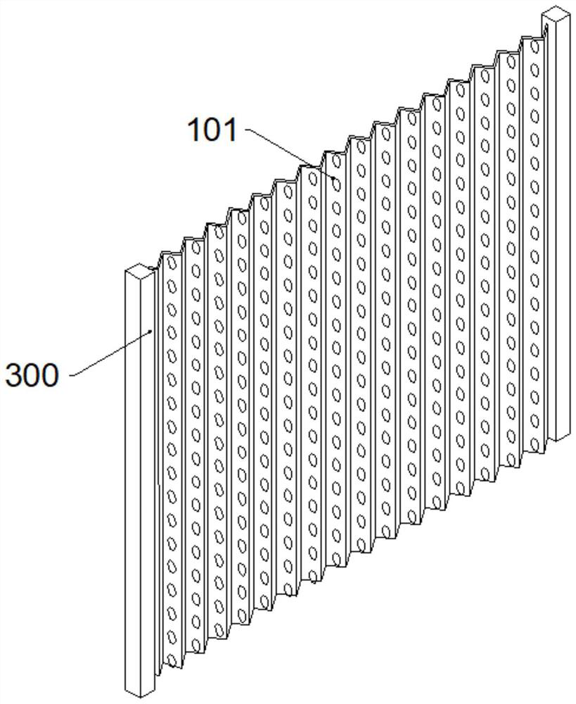
[0049] Such as Figure 1~4 An assembled double-layer corrugated steel plate composite shear wall is shown, the shear wall includes two vertical steel pipes 300 and a prefabricated shear wall 100 assembled in the two vertical steel pipes 300, the prefabricated shear wall 100 includes steel plates Mechanism 101, two groups of reinforcement mesh 102. Two groups of reinforcement meshes 102 are respectively fixedly installed on opposite side walls of the steel plate mechanism 101 . A concrete layer 103 is poured on the outside of the reinforcement mesh 102 .

[0050] The two sides of the upper end of the steel plate mechanism 101 are respectively welded and fixed with embedded inserting plates 400. The embedded inserting plates 400 are corrugated and compatible with the steel plate mechanism 101. The lower ends of the steel plate mechanism 101 are respectively provided with embedded inserting plates 400. The matching slot 401, the pre-embedded slot 400, the concrete layer 103 on ...

Embodiment 2

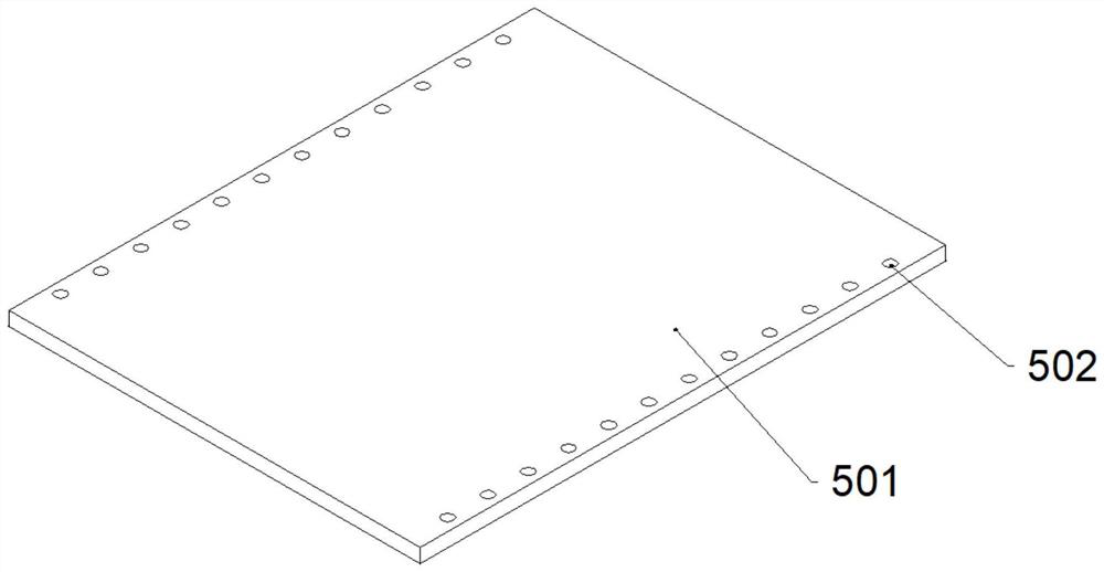
[0059] Such as Figure 5-11 An assembled double-layer corrugated steel plate composite shear wall is shown, the shear wall includes two vertical steel pipes 300 and a prefabricated shear wall 100 assembled in the two vertical steel pipes 300, the prefabricated shear wall 100 includes steel plates Mechanism 101, two groups of reinforcement mesh 102. Two groups of reinforcement meshes 102 are respectively fixedly installed on opposite side walls of the steel plate mechanism 101 . A concrete layer 103 is poured on the outside of the reinforcement mesh 102 .

[0060] The two sides of the upper end of the steel plate mechanism 101 are respectively welded and fixed with pre-embedded inserting plates 400, and the two sides of the lower end of the steel plate mechanism 101 are respectively provided with insertion slots 401 compatible with the embedded inserts 400, the embedded inserts 400 and the inserting slots 401 The concrete layer 103 on both sides and the lower end of the steel...

Embodiment 3

[0071] Such as Figures 12 to 14 An assembled double-layer corrugated steel plate composite shear wall is shown, the shear wall includes two vertical steel pipes 300 and a prefabricated shear wall 100 assembled in the two vertical steel pipes 300, the prefabricated shear wall 100 includes steel plates Mechanism 101, two groups of reinforcement mesh 102. Two groups of reinforcement meshes 102 are respectively fixedly installed on opposite side walls of the steel plate mechanism 101 . A concrete layer 103 is poured on the outside of the reinforcement mesh 102 .

[0072] The two sides of the upper end of the steel plate mechanism 101 are respectively welded and fixed with pre-embedded inserting plates 400, and the two sides of the lower end of the steel plate mechanism 101 are respectively provided with insertion slots 401 compatible with the embedded inserts 400, the embedded inserts 400 and the inserting slots 401 The concrete layer 103 on both sides and the lower end of the ...


PUM


Abstract

The invention relates to a fabricated double-layer corrugated steel plate composite shear wall and a splicing method thereof. The fabricated double-layer corrugated steel plate composite shear wall comprises two vertical square steel pipes and a prefabricated shear wall assembled in the two vertical square steel pipes, wherein two reinforcing meshes in the prefabricated shear wall are fixedly installed on the two opposite side walls of a steel plate mechanism correspondingly, concrete layers are poured outside the reinforcing meshes, pre-embedded inserting plates are fixedly installed on the two sides of the upper end of the steel plate mechanism correspondingly, inserting grooves matching with the pre-embedded inserting plates are formed in the two sides of the lower end of the steel plate mechanism correspondingly, the pre-embedded inserting plates, the concrete layers on the two sides of the inserting grooves and the lower end of the steel plate mechanism are provided with matching first steel bar through holes, steel bars are arranged in the first steel bar through holes in an inserted mode, and superimposed sheet bottom plates are assembled on the prefabricated shear wall. The problems that according to an existing connection mode of fabricated shear walls and shear walls and a connection mode of the shear walls and prefabricated floor slabs, the integrity of the shear walls and the prefabricated floor slabs after assembly is poor, construction is inconvenient and not stable enough, multiple splicing cannot be realized, the operation is tedious, and the construction efficiency is low are solved.

Description

technical field [0001] The invention belongs to the technical field of prefabricated buildings, and in particular relates to a prefabricated double-layer corrugated steel plate composite shear wall and a splicing method thereof. Background technique [0002] With the transformation of the national economy and the adjustment of the industrial structure, my country's construction production mode will change from the traditional manual workshop-style "construction" mode with high energy consumption and low output to the factory-like and standardized "manufacturing" mode. Because of its high structural rigidity, good bearing capacity and flexible space layout, and in line with the development requirements of "housing industrialization", the type shear wall structure has begun to be popularized and applied nationwide. Compared with the prefabricated frame structure, there are more horizontal joints in the prefabricated shear wall structure. These joints not only directly determine...

Claims


Application Information

Patent Timeline
Patent Type & Authority Applications(China)
IPC IPC(8): E04H9/02E04B1/98
CPCE04H9/021E04B1/98Y02B80/10
Inventor 白久林梁媛彭雄王宇航杨庆山杨经纬
Owner CHONGQING UNIV
Learn More