
Method for simulating crack in oil reservoir and device and method for burying monitoring elements of crack in oil reservoir

A technology for simulating oil and components, applied in the field of geomechanical model test, can solve the problems of inability to bury monitoring components, complicated operation, and great influence on experimental results, and achieves the effects of easy burying of monitoring components, low cost, and wide application.

Pending Publication Date: 2021-09-24
CHINA PETROLEUM & CHEM CORP +1
View PDF9 Cites 0 Cited by
  • Summary
  • Abstract
  • Description
  • Claims
  • Application Information

AI Technical Summary

Problems solved by technology

[0007] The existing methods of making prefabricated cracks are all based on filling the cracks, which cannot consider the fact that the cracks are cavities, and cannot bury monitoring elements around the cracks without filling; the existing prefabricated crack technology mostly uses splicing installation, which artificially increases The weak surface is exposed, which has a great influence on the experimental results; and the existing prefabricated crack technology is mostly for small test pieces, and most of them use methods such as drilling and grooving, which cannot be used in large-scale model tests.
However, the embedding method of monitoring elements in the prior art is complicated to operate and cannot be accurately positioned, which has a great impact on the stability of prefabricated cracks during embedding.

Method used


Image

  • Method for simulating crack in oil reservoir and device and method for burying monitoring elements of crack in oil reservoir
  • Method for simulating crack in oil reservoir and device and method for burying monitoring elements of crack in oil reservoir
  • Method for simulating crack in oil reservoir and device and method for burying monitoring elements of crack in oil reservoir

Examples


Embodiment Construction

[0050] The present invention will be further described in detail below in conjunction with the accompanying drawings and specific embodiments. It should be noted that, as long as there is no conflict, each embodiment and each feature in each embodiment of the present invention can be combined with each other, and the formed technical solutions are all within the protection scope of the present invention.

[0051]Unless otherwise defined, the technical terms or scientific terms used in the present invention shall have the usual meanings understood by those skilled in the art to which the present invention belongs. The terms "first", "second" and similar words used in the present invention do not indicate any order, quantity or importance, but are only used to distinguish different components. "Comprising" or "comprising" and similar words mean that the elements or items appearing before the word include the elements or items listed after the word and their equivalents, without ...


PUM

PropertyMeasurementUnit
heightaaaaaaaaaa

Abstract

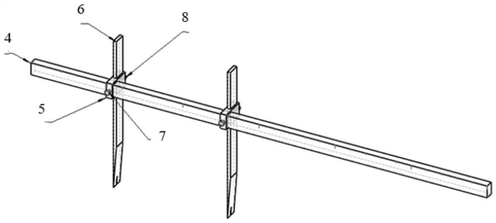
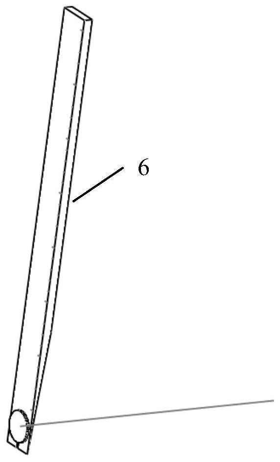
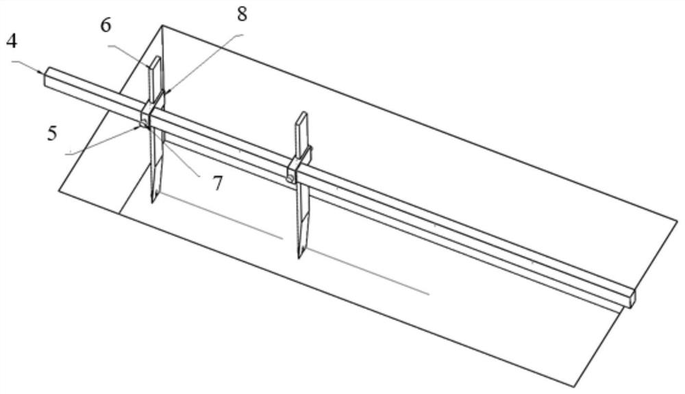
The invention provides a method for simulating a crack in an oil reservoir and a device and a method for burying peripheral monitoring elements of the crack in the oil reservoir, and the method for simulating the crack in the oil reservoir comprises the following steps: compacting a model layer by layer to a preset height, and digging a space required by the crack and the buried elements downwards; placing a hard insulating plate at the position where the crack is located, then embedding a monitoring element, and filling the space with a similar material and compacting the space; pulling out the hard insulating plate to form a crack cavity; laying a polymer film on the crack cavity and fixing the film, laying a small amount of similar materials on the film and hammered slightly, and finally completing a crack upper model body through a layered compaction method. By using the method provided by the invention, the monitoring element can be accurately positioned and embedded, and any number of cracks can be manufactured; no filling in the crack is completely achieved, no extra weak surface is added to the model body, the expected target of the model test for the crack in the fracture-cavity body can be achieved, and accurate experimental data can be obtained.

Description

technical field [0001] The invention relates to the field of geomechanical model tests, in particular to a monitoring element embedding device and embedding method used in petroleum and other fields, and a method for prefabricating cracks inside the geomechanical model test. Background technique [0002] Ordovician fractured-vuggy carbonate reservoirs in Tahe Oilfield are complex and particular, the reservoir type is mainly dissolved caves, and the storage space of fractured caved carbonate reservoirs is mainly composed of two basic structures: dissolved caves and fractures Among them, the cave is the main storage space, and the fracture mainly plays the role of communication between the caves. In the process of oil production, as the formation pressure drops, it is easy to lead to the collapse of caves or the closure of oil outlet channels in large fractures, which seriously affects the production of oil wells and the recovery factor of oil reservoirs. The current breakthr...

Claims


Application Information

Patent Timeline
Patent Type & Authority Applications(China)
IPC IPC(8): G01N33/24G01V99/00G09B23/40
CPCG01N33/24G09B23/40G01V20/00
Inventor 吕心瑞孙建芳丁炎志张强勇魏荷花邬兴威解丽慧李红凯韩科龙卜翠萍
Owner CHINA PETROLEUM & CHEM CORP
Learn More