Industrial fireproof heat-insulation fiber cloth pasting and dyeing device
A dyeing device and fiber cloth technology, applied in textiles and papermaking, liquid/gas/steam textile material treatment, removal of liquid/gas/steam, etc., can solve the problems of large amount of operation and low efficiency, and achieve the effect of easy collection
- Summary
- Abstract
- Description
- Claims
- Application Information
AI Technical Summary
Problems solved by technology
Method used
Image
Examples
Embodiment 1
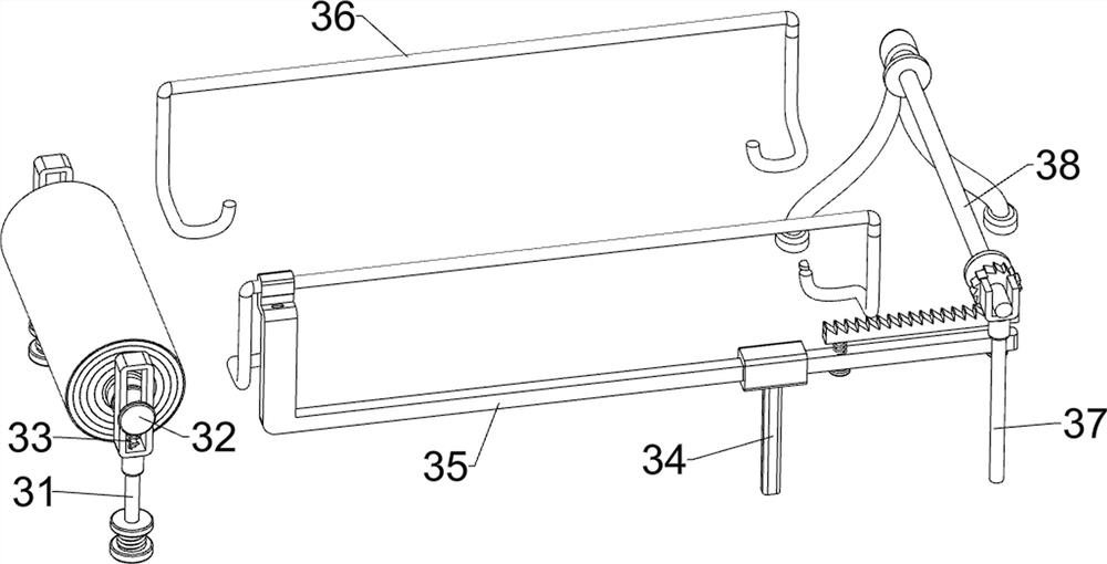
[0045] A kind of industrial fireproof heat insulation fiber cloth pasting dyeing device, such as Figure 1 to Figure 3 As shown, it includes a base 1 , a driving mechanism 2 and a rolling mechanism 3 , the top of the base 1 is provided with a driving mechanism 2 and a rolling mechanism 3 , and the driving mechanism 2 is located inside the rolling mechanism 3 .
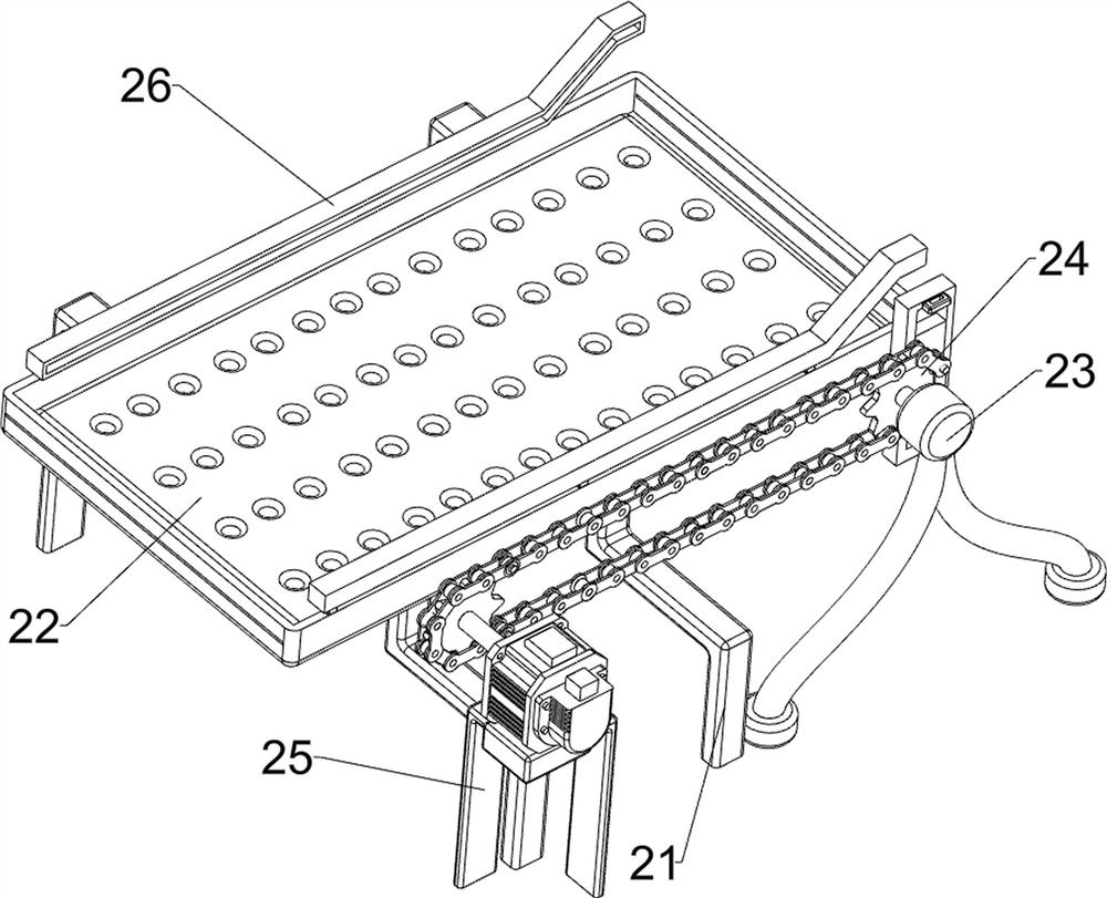
[0046] The driving mechanism 2 includes a fixed frame 21, a sponge 22, a first fixed rod 23, a sprocket assembly 24, a motor 25, and a slide bar 26. The top of the base 1 is provided with a fixed frame 21, and the top of the fixed frame 21 inner wall is provided with a sponge 22. Frame 21 top front and rear sides are all provided with slide bar 26, base 1 top right front side is provided with first fixed rod 23, base 1 top left front side is provided with motor 25, between the output shaft of motor 25 and first fixed rod 23 tops The rotary type is provided with a sprocket assembly 24 .
[0047] The rolling mechanism 3...
Embodiment 2
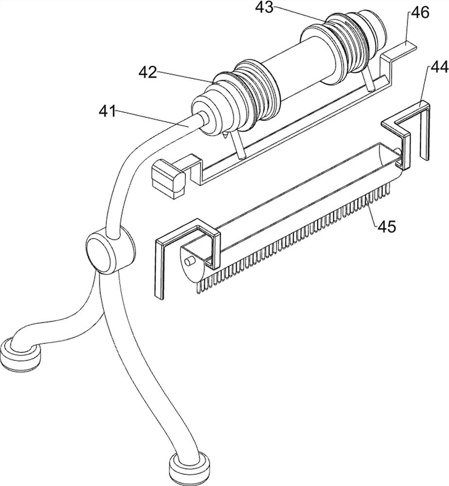
[0050] On the basis of Example 1, such as Figure 4 As shown, a feeding mechanism 4 is also included, and the feeding mechanism 4 includes a bucket 41, a switch 42, a second spring 43, a material frame 44, a brush 45 and a stopper 46, and the top of the first fixed rod 23 is provided with a bucket 41, Both front and back parts of the material barrel 41 are rotatably provided with a switch 42, a second spring 43 is connected between the switch 42 and the material barrel 41, and a material frame 44 is slidably connected between the slide bars 26, and the material frame 44 is slidably connected with the sliding frame , The bottom of the material frame 44 is provided with a brush 45, and a block 46 is connected between the slide bars 36, and both sides of the block 46 are respectively connected with the sliding frame and the thorn rack of the thorn tooth assembly 35.
[0051]Start the motor 25, the output shaft of the motor 25 rotates through the sprocket assembly 24 to drive the ...
Embodiment 3
[0053] On the basis of Example 2, such as Figure 5 to Figure 7 As shown, it also includes an air-drying mechanism 5. The air-drying mechanism 5 includes a fixed plate 51, a motor 52, a fan blade 53, a second transmission assembly 54, a scraper 55, a telescopic rod 56 and a third spring 57. The left side of the fixed frame 21 bottom is The side is provided with a fixed plate 51, the bottom of the fixed plate 51 is provided with a motor 52, and the top of the fixed plate 51 is provided with three fan blades 53 in a rotating manner. There is a second transmission assembly 54 connected between them, a telescopic rod 56 is symmetrically arranged on the left side of the top of the fixed frame 21, a scraper 55 is symmetrically connected between the bottom of the telescopic rod 56, and a third connecting rod is connected between the top of the scraper 55 and the telescopic rod 56. Spring 57.
[0054] It also includes an impurity removal mechanism 6, which includes a fourth fixed rod...
PUM
 Abstract
Description
Claims
Application Information
 - R&D
- Intellectual Property
- Life Sciences
- Materials
- Tech Scout
- Unparalleled Data Quality
- Higher Quality Content
- 60% Fewer Hallucinations
Browse by: Latest US Patents, China's latest patents, Technical Efficacy Thesaurus, Application Domain, Technology Topic, Popular Technical Reports.
© 2025 PatSnap. All rights reserved.Legal|Privacy policy|Modern Slavery Act Transparency Statement|Sitemap|About US| Contact US: help@patsnap.com


