A paste dyeing device for industrial fire-proof and heat-insulating fiber cloth

A dyeing device and fiber cloth technology, applied in the field of dyeing devices, can solve the problems of large operation volume and low efficiency, and achieve the effect of easy collection

Active Publication Date: 2022-04-19
钟丹敏
View PDF0 Cites 0 Cited by
  • Summary
  • Abstract
  • Description
  • Claims
  • Application Information

AI Technical Summary

Problems solved by technology

[0003] In the use of some specific fiber cloth, it is necessary to color the fiber cloth for the subsequent production of more brightly colored fiber products. Generally, it is necessary to manually immerse the fiber cloth in the pigment, and then take it out to dry. Large size and low efficiency, so it is necessary to design an industrial fire-proof and heat-insulating fiber cloth paste dyeing device that relies on the machine to dye the fiber cloth while winding it to improve efficiency

Method used


Image

  • A paste dyeing device for industrial fire-proof and heat-insulating fiber cloth
  • A paste dyeing device for industrial fire-proof and heat-insulating fiber cloth
  • A paste dyeing device for industrial fire-proof and heat-insulating fiber cloth

Examples


Embodiment 1

[0045] A kind of industrial fireproof heat insulation fiber cloth pasting dyeing device, such as Figure 1 to Figure 3 As shown, it includes a base 1 , a driving mechanism 2 and a rolling mechanism 3 , the top of the base 1 is provided with a driving mechanism 2 and a rolling mechanism 3 , and the driving mechanism 2 is located inside the rolling mechanism 3 .

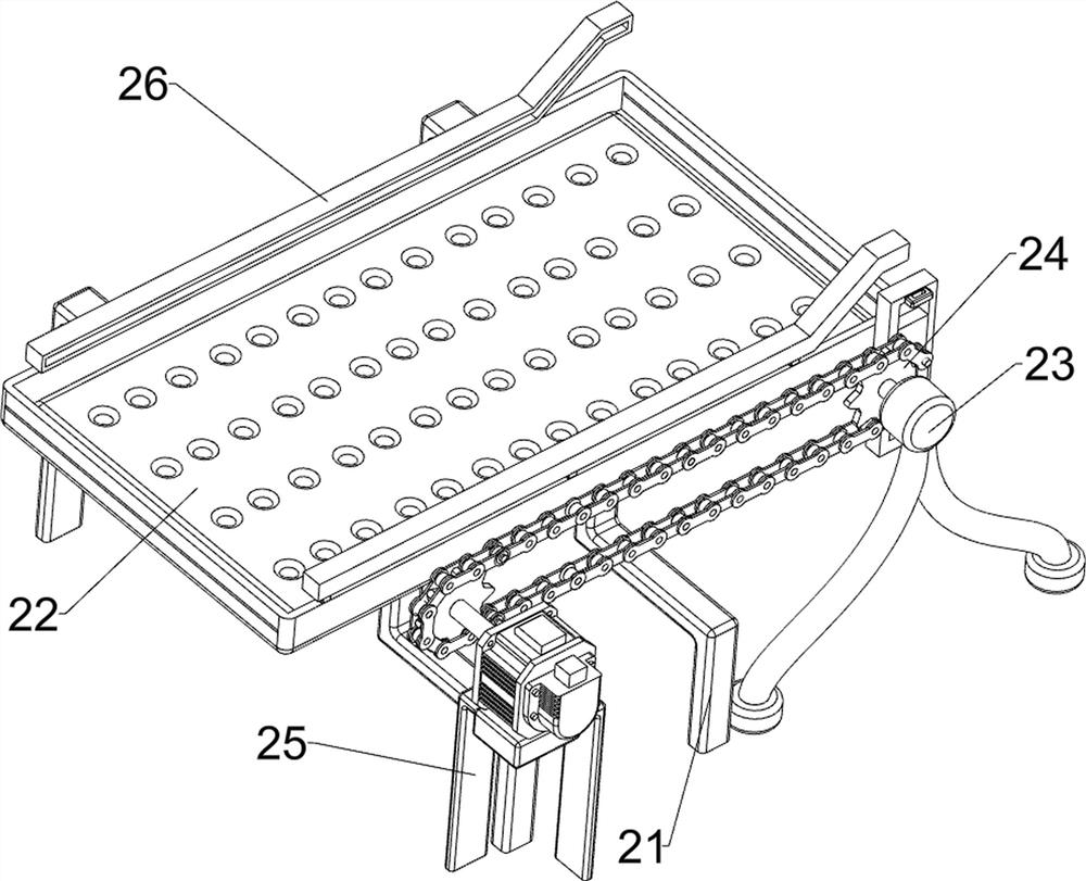
[0046] The driving mechanism 2 includes a fixed frame 21, a sponge 22, a first fixed rod 23, a sprocket assembly 24, a motor 25, and a slide bar 26. The top of the base 1 is provided with a fixed frame 21, and the top of the fixed frame 21 inner wall is provided with a sponge 22. Frame 21 top front and rear sides are all provided with slide bar 26, base 1 top right front side is provided with first fixed rod 23, base 1 top left front side is provided with motor 25, between the output shaft of motor 25 and first fixed rod 23 tops The rotary type is provided with a sprocket assembly 24 .

[0047] The rolling mechanism 3...

Embodiment 2

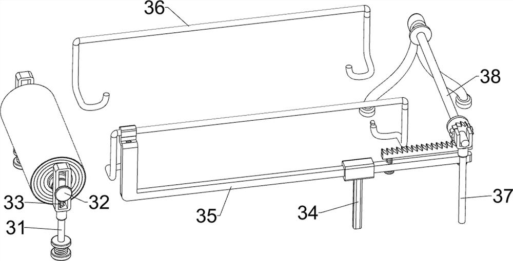
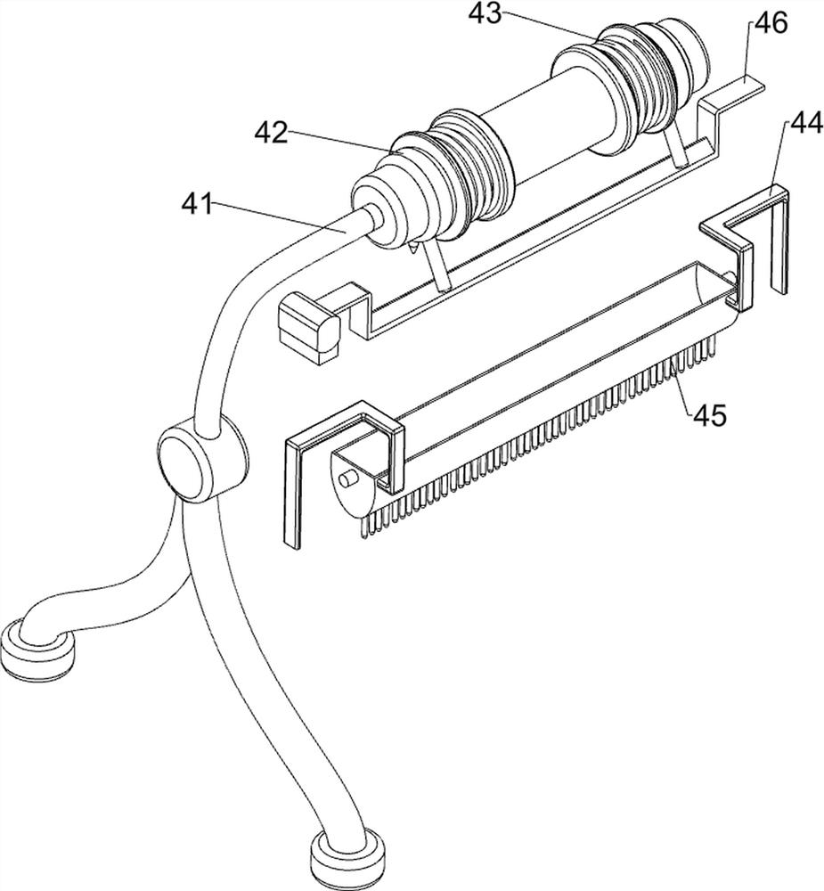
[0050] On the basis of Example 1, such as Figure 4 As shown, a feeding mechanism 4 is also included, and the feeding mechanism 4 includes a bucket 41, a switch 42, a second spring 43, a material frame 44, a brush 45 and a stopper 46, and the top of the first fixed rod 23 is provided with a bucket 41, Both front and back parts of the material barrel 41 are rotatably provided with a switch 42, a second spring 43 is connected between the switch 42 and the material barrel 41, and a material frame 44 is slidably connected between the slide bars 26, and the material frame 44 is slidably connected with the sliding frame , The bottom of the material frame 44 is provided with a brush 45, and a block 46 is connected between the slide bars 36, and both sides of the block 46 are respectively connected with the sliding frame and the thorn rack of the thorn tooth assembly 35.

[0051]Start the motor 25, the output shaft of the motor 25 rotates through the sprocket assembly 24 to drive the ...

Embodiment 3

[0053] On the basis of Example 2, such as Figure 5 to Figure 7 As shown, it also includes an air-drying mechanism 5. The air-drying mechanism 5 includes a fixed plate 51, a motor 52, a fan blade 53, a second transmission assembly 54, a scraper 55, a telescopic rod 56 and a third spring 57. The left side of the fixed frame 21 bottom is The side is provided with a fixed plate 51, the bottom of the fixed plate 51 is provided with a motor 52, and the top of the fixed plate 51 is provided with three fan blades 53 in a rotating manner. There is a second transmission assembly 54 connected between them, a telescopic rod 56 is symmetrically arranged on the left side of the top of the fixed frame 21, a scraper 55 is symmetrically connected between the bottom of the telescopic rod 56, and a third connecting rod is connected between the top of the scraper 55 and the telescopic rod 56. Spring 57.

[0054] It also includes an impurity removal mechanism 6, which includes a fourth fixed rod...


PUM


Abstract

The invention relates to a dyeing device, in particular to a pasting dyeing device for industrial fire-proof and heat-insulating fiber cloth. The main purpose is to provide an industrial fire-proof and heat-insulating fiber cloth pasting and dyeing device that relies on the machine to dye and wind the fiber cloth while improving the efficiency. An industrial fire-proof and heat-insulating fiber cloth pasting and dyeing device includes: a base, a driving mechanism and a rolling mechanism are arranged on the top of the base, and the driving mechanism is located inside the rolling mechanism. By setting a driving mechanism, a rolling mechanism and a feeding mechanism, the cloth is driven to be pulled out and tightened while being in contact with the sponge with pigments, thereby realizing the dyeing of the cloth.

Description

technical field [0001] The invention relates to a dyeing device, in particular to a pasting dyeing device for industrial fire-proof and heat-insulating fiber cloth. Background technique [0002] Fiber cloth, also known as carbon fiber cloth, is known as "black gold" internationally. After metals such as stone tools and steel, it is called "third-generation material" internationally, because the composite material made of carbon fiber The material has extremely high strength, is ultra-light, and is resistant to high temperature and pressure. [0003] In the use of some specific fiber cloth, it is necessary to color the fiber cloth for the subsequent production of more brightly colored fiber products. Generally, it is necessary to manually immerse the fiber cloth in the pigment, and then take it out to dry. Large size and low efficiency, so it is necessary to design an industrial fire-proof and heat-insulating fiber cloth pasting and dyeing device that relies on the machine t...

Claims


Application Information

Patent Timeline
Patent Type & Authority Patents(China)
IPC IPC(8): D06B1/12D06B15/00D06B15/08D06B23/04
CPCD06B1/12D06B23/04D06B15/00D06B15/085
Inventor 钟丹敏
Owner 钟丹敏
Why Eureka
Try Eureka