Heat dissipation type relay with breathing function

A breathing function, relay technology, applied in relay ventilation/cooling/heating, separation of dispersed particles, chemical instruments and methods, etc., can solve the problems of low thermal conductivity, unfavorable relay operation, etc., and achieve the effect of easy operation

Active Publication Date: 2021-09-28
中汇瑞德电子(芜湖)有限公司
View PDF7 Cites 2 Cited by
  • Summary
  • Abstract
  • Description
  • Claims
  • Application Information

AI Technical Summary

Problems solved by technology

[0004] The disadvantage of the existing technology is that most of the existing relays pass through the metal heat sink when the temperature is lowered, and when the relay is working, there is a gap between the heat sink, the coil and the a

Method used


Image

  • Heat dissipation type relay with breathing function
  • Heat dissipation type relay with breathing function
  • Heat dissipation type relay with breathing function

Examples


Embodiment 1

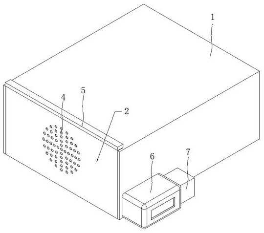
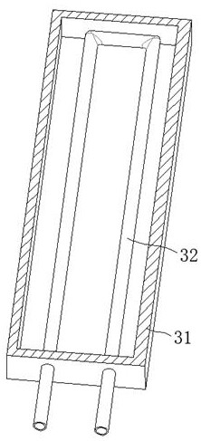
[0034] like Figure 1 to Figure 3 As shown, when the relay body 9 is working, the compressor 7 compresses the air and sends the compressed air into the U-shaped evaporating tube 32. At this time, the air temperature in the U-shaped evaporating tube 32 is relatively low, and the cooling box 31 and the protection box 1, the heat-absorbing air enters the condenser 6 from the output end of the U-shaped evaporating tube 32, and releases heat from the condenser 6, and then sends the air into the compressor 7 for compression, and repeats the process. Continuously reduce the temperature in the protection box 1, maintain the maximum average current on the relay body 9, and avoid the derating of the relay body 9 caused by the temperature of the relay body 9 being too high. melting deformation.

Embodiment 2

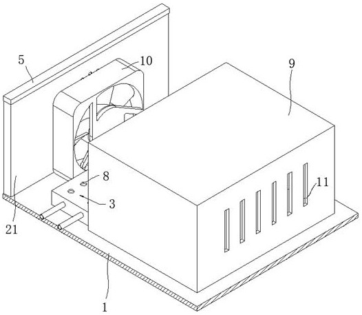
[0036] like figure 2As shown, a fan 10 is installed in the protection box 1, and the cold air produced by the cooling unit 3 flows into the protection box 1 from the through hole 8, and the cool air is blown to the relay body 9 by the fan 10, and at the same time, the relay body 9 phase Convection grooves 11 are provided on the side adjacent to the fan 10 and the side opposite to the fan 10 , and the air flow will send cold air into the relay body 9 to reduce the temperature in the relay body 9 .

Embodiment 3

[0038] like figure 1 and figure 2 As shown, a temperature sensor is installed in the protection box 1 to detect the temperature in the protection box 1. When the temperature is too high, the cooling unit 3 is activated to reduce the temperature of the relay body 9. When the temperature is low, the cooling unit 3 is turned off. , make the cooling unit 3 stop absorbing heat, make the temperature in the protection box 1 rise slowly, and keep the temperature in the protection box 1 within the operating temperature of the relay body 9 .


PUM


Abstract

The invention relates to the technical field of heat dissipation type relays with a breathing function, and discloses a heat dissipation type relay with a breathing function. The relay comprises a protection box with an opening in one side and a relay body fixedly mounted at the bottom of the inner wall of the protection box, a filter unit is arranged at the opening of the protection box, and a cooling unit is arranged in the protection box. When the cooling unit reduces the temperature of the relay body, moisture in air is prevented from entering the protection box through the filtering unit, heat in the protection box is absorbed through a U-shaped evaporation pipe, the maximum average current on the relay body is maintained, and meanwhile the temperature is too high so that insulation aging of the relay body and fusing deformation of a coil shell can be caused. Water in the air is contained in a high-water-absorption polymer bag, damage of water molecules to an internal circuit of the relay body is avoided, after the high-water-absorption polymer bag absorbs water and expands, the high-water-absorption polymer bag can be lifted out of a fixing frame by pulling up a sealing cover, and operation of maintenance personnel is facilitated.

Description

technical field [0001] The invention relates to the technical field of heat dissipation relays with breathing function, in particular to a heat dissipation relay with breathing function. Background technique [0002] The relay is an electronic control device, which has a control system and a controlled system, and is usually used in automatic control circuits. [0003] According to the patent No. 201911184749.5, a heat dissipation structure of a current load relay is disclosed, which includes a corner seat and an inner pull mechanism. The pulling mechanism is placed on the left side of the top of the corner seat, and the upper end of the corner seat and the socket is equipped with an upper seat, and the end of the upper seat is fixed with a heat dissipation mechanism. There is a side groove, and an inner ring is arranged in the middle of the side groove, a perforation is installed on the inner side of the side groove, and a threaded post is arranged at the inner end of the ...

Claims


Application Information

Patent Timeline
IPC IPC(8): H01H45/12H01H45/02B01D53/26
CPCH01H45/12H01H45/02B01D53/26
Inventor 杜展
Owner 中汇瑞德电子(芜湖)有限公司
Why Eureka
Try Eureka