Power equipment monitoring system

A monitoring system and power equipment technology, which is applied in the direction of anti-seismic equipment, substation/power distribution device housing, etc., can solve the problems that the camera cannot cope with external interference, the surveillance camera does not have a hidden function, and interferes with the normal operation of the camera, etc., to achieve Reduce the degree of man-made damage, increase concealment, and have excellent camouflage effects

Active Publication Date: 2021-09-28
广东创亚电气集团有限公司
View PDF9 Cites 0 Cited by
  • Summary
  • Abstract
  • Description
  • Claims
  • Application Information

AI Technical Summary

Problems solved by technology

[0004] Existing cameras cannot cope with external disturbances in the working process, such as the building of bird nests and the standing of birds, which greatly interfere with the normal operation of the camera and easily cause damage to the camera body. At the same time, the existing monitoring The camera does not have a good concealment function, and the well-known power equipment is usually expensive, so many people with a heart are motivated to commit crimes. The existing cameras still need to be improved in terms of protection and anti-theft

Method used


Image

  • Power equipment monitoring system
  • Power equipment monitoring system
  • Power equipment monitoring system

Examples


Embodiment Construction

[0034] The following will clearly and completely describe the technical solutions in the embodiments of the present invention with reference to the accompanying drawings in the embodiments of the present invention. Obviously, the described embodiments are only some, not all, embodiments of the present invention. Based on the embodiments of the present invention, all other embodiments obtained by persons of ordinary skill in the art without making creative efforts belong to the protection scope of the present invention.

[0035] see Figure 1 to Figure 6 , the present invention provides a technical solution:

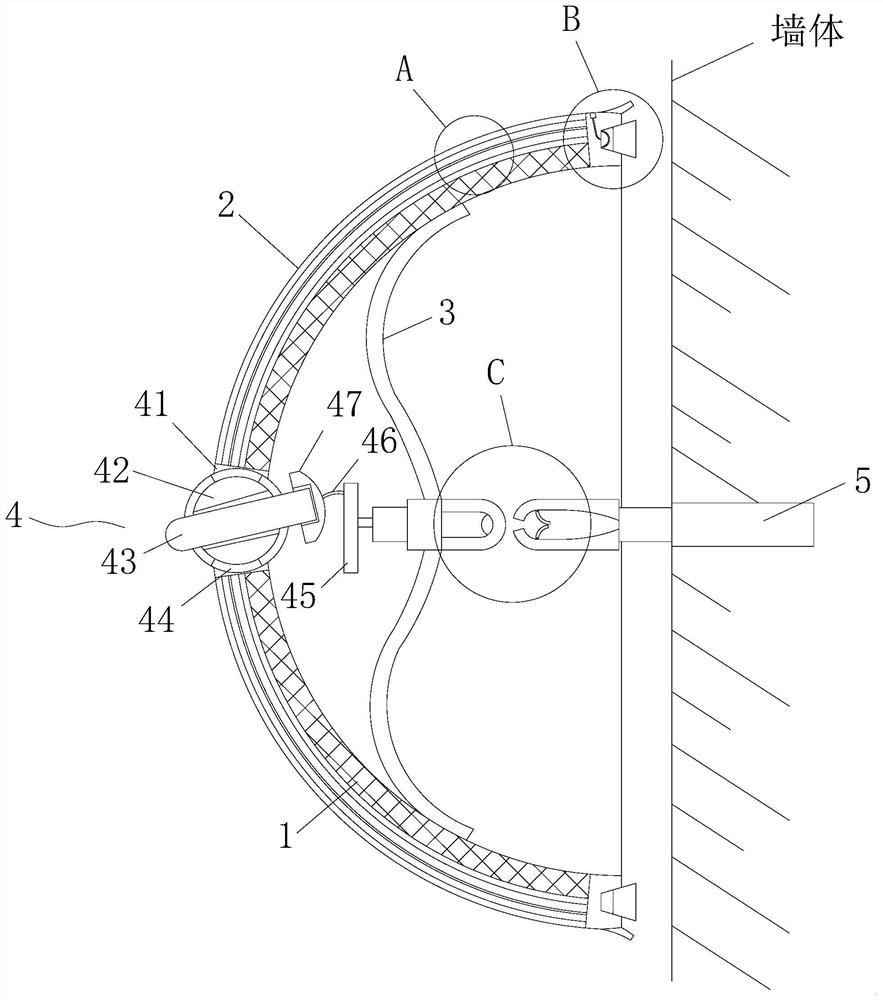
[0036] Such as figure 1 As shown, a power equipment monitoring system includes an inner casing 1 and an outer casing 2, the outer casing 2 is hinged and fixed on the outer surface of the inner casing 1, and both of them are designed in a hemispherical structure as a whole, and the inner casing The inner surface of the body 1 is fixed with an elastic sheet 3, and the lef...


PUM


Abstract

A power equipment monitoring system disclosed by the present invention comprises an inner shell and an outer shell, the outer shell is hinged and fixed to the outer surface of the inner shell, the outer shell and the inner shell are integrally of a hemispherical structure design, an elastic sheet is fixed to the inner surface of the inner shell, an adjusting assembly is arranged on the left side of the middle of the elastic sheet, and a locking assembly is arranged on the right side of the middle of the elastic sheet. An expansion screw is arranged at the corresponding position of the right side of the locking assembly, and sealing assemblies are arranged on the annular faces of the right sides of the inner shell and the outer shell. The locking assembly is arranged to be matched with the elastic piece, the insertion strip and the butt joint strip in the locking assembly are correspondingly inserted in a staggered mode, after the insertion strip and the butt joint strip are connected, elastic reset and rebound are further achieved through the elastic piece, the opening position is closed through deformation of an upper stirring piece and a lower stirring piece, and connection and fixing work is completed. The device is simple in structure and simple to operate. Compared with an existing external fixing mode, certain hiding performance is achieved, the whole device cannot be disassembled and damaged rapidly through the outside, and therefore the degree of man-made damage to the device is reduced.

Description

technical field [0001] The invention relates to the technical field of power equipment monitoring, in particular to a power equipment monitoring system. Background technique [0002] The monitoring equipment is also called the monitoring system, and its main part is the video monitoring equipment to record the designated area, and after the power equipment is installed, the monitoring device needs to monitor its operating status in real time; [0003] The most important equipment in video surveillance equipment is the camera, which can be divided into network digital cameras and analog cameras, which can be used as front-end video image signal collection. The video surveillance system is a comprehensive system with strong preventive capabilities. Video surveillance is characterized by its intuitive , Accurate, timely and rich in information content and widely used in many occasions; in recent years, with the rapid development of computer, network, image processing and transm...

Claims


Application Information

Patent Timeline
IPC IPC(8): H02B1/54H02B1/26H02B1/28
CPCH02B1/54H02B1/26H02B1/28
Inventor 连盟徐志永
Owner 广东创亚电气集团有限公司
Why Eureka
Try Eureka