Control method of food processor

A technology of a food processing machine and a control method, which is applied to heating, cooking utensils, household appliances, etc., can solve the problem of using too much cleaning water, and achieve the effect of simple scheme and good cleaning and disinfection effect

Pending Publication Date: 2021-10-01
JOYOUNG CO LTD
View PDF2 Cites 0 Cited by
  • Summary
  • Abstract
  • Description
  • Claims
  • Application Information

AI Technical Summary

Problems solved by technology

In the above scheme, since there is an infiltration stage before the fumigation, under the effect of high temperature, the steam can better soften the residue, but the cleaning process still needs to enter the water many times, and the whipping of the pulverizing blade is used to realize the cleaning process. The scouring of the inner wall of the crushing chamber can realize the cleaning of residues. Therefore, the food processing machine in the above application needs to be washed with water for many times, and the amount of cleaning water is also used more.

Method used


Image

  • Control method of food processor
  • Control method of food processor

Examples


Embodiment 1

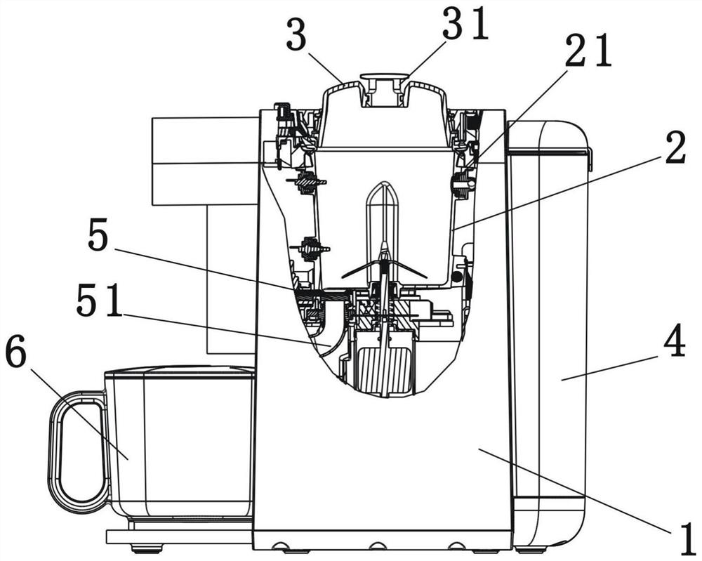
[0034] Such as figure 1As shown, it is a food processor according to the first embodiment of the present invention, a food processor comprising a body 1, a crushing cup 2 installed in the body 1 and a cup cover 3 mounted on the top of the crushing cup 2. A silica gel plug 31 is installed on the cup cover 3, and the pulverizing cup 2 and the cup cover 3 are enclosed to form a non-closed pulping chamber. Simultaneously, a water tank 4 is installed on one side of the body 1, and a heating device (not shown) that heats the water tank and generates steam is arranged in the water tank 4, wherein the cup wall of the crushing cup 2 is provided with a The water inlet or steam inlet nozzle 21 of the crushing cup 2 is fed into, wherein the water inlet nozzle 21 is communicated with the water tank 4 through a pipeline (not shown in the figure). Wherein, the water tank 4 and the heating device form a steam generating device for feeding steam into the pulping chamber. In addition, the bot...

Embodiment 2

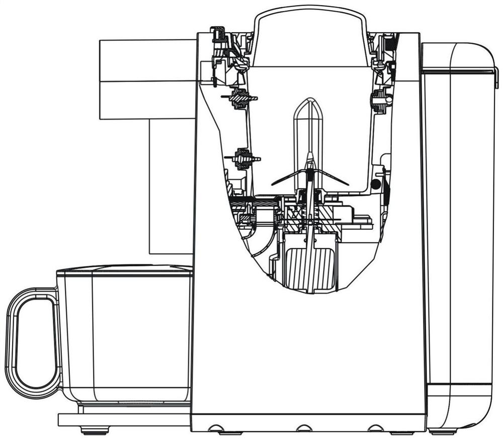
[0043] Such as figure 2 Shown is a schematic structural diagram of the second embodiment of the present invention. The difference between this embodiment and the first embodiment is that in this embodiment, the cup cover has no air holes and no silicone plugs, and the pulping chamber formed by the cup cover and the pulverizing cup is a cavity with a closed structure. When steam is introduced into the pulping chamber, the liquid discharge assembly is the only outlet for the steam to discharge.

[0044] For the food processor of this embodiment, thick soybean milk can be prepared. Its pulping process has the following steps:

[0045] 1) Preparation stage

[0046] 2) Pulping stage: the pulverizing blade beats and pulverizes the mixture of the material and water in the pulping chamber to prepare thick raw pulp mixed with pulp juice and pulp residue.

[0047] 3) Juice discharge stage: open the liquid discharge assembly, and the pulp juice and pulp residue mixed with the pulp j...


PUM


Abstract

The invention relates to a control technology of kitchen household appliances, in particular to a control method of a food processor, the food processor comprises a pulping chamber, a liquid discharge assembly for controlling the pulping chamber to be opened and closed, and a steam generating device for introducing steam into the pulping chamber, the control method is characterized by comprising the steps that when the liquid discharging assembly is in an open state, the steam generating device introduces steam into the pulping cavity, and the steam is discharged out of the pulping cavity through the liquid discharging assembly. According to the food processing machine adopting the control method, in the cleaning process, impurities (stains, residues or pulp residues) in the pulping chamber can be discharged through steam without cleaning water or with little cleaning water, and moreover, the method can realize automatic sterilization, disinfection, automatic pulp discharging and residue discharging of the food processing machine, hand washing is not needed, and even the soybean milk is automatically heated.

Description

technical field [0001] The invention relates to a control technology of kitchen appliances, in particular to a control method of a food processing machine. Background technique [0002] In the existing soymilk machines that can automatically produce milk, when preparing soymilk drinks, materials and water are generally added according to the ratio requirements, but in actual use, consumers will add materials and water to the soymilk machine at will for simplicity and convenience. In this way, it may happen that more materials are added and less water is added. After the soybean milk machine is finished, the soybean milk is thicker and contains more slag. In the process of automatic slurry discharge, the flowing pulp will be discharged quickly, but the pulp residue with poor fluidity cannot be completely discharged, and will still remain in the crushing cup of the soybean milk machine. Therefore, it is necessary to add water to the soybean milk machine many times to flush ou...

Claims


Application Information

Patent Timeline
IPC IPC(8): A47J43/046A47J43/07A47J27/04A61L2/07
CPCA47J43/046A47J43/0716A47J27/04A61L2/07A47J2027/043
Inventor 王旭宁黄皓陈龙郭红伟
Owner JOYOUNG CO LTD
Why Eureka
Try Eureka