
Wind turbine vane shaping device

A technology for wind power blades and trimming parts, which is applied in the field of trimming devices for wind power blades, can solve the problems of easily affecting the operation, the trimming angle cannot be adjusted, and the stability of the unit is affected, so as to achieve the effect of saving construction costs and protecting the blades.

Pending Publication Date: 2021-10-01
华能威宁风力发电有限公司 +1
View PDF13 Cites 0 Cited by
  • Summary
  • Abstract
  • Description
  • Claims
  • Application Information

AI Technical Summary

Problems solved by technology

[0002] A wind turbine is a power device that converts wind energy into mechanical energy, which drives the rotor to rotate, and finally outputs alternating current. Once the blades of the wind turbine have problems, it will not only incur huge maintenance and replacement costs, but also affect the stability of the unit. There is a patent, patent number: 2019219186369, patent name: a new type of tooling for wind turbine blade leading edge repair, which solves the problem that the existing repair requires staff to operate with both hands, and the repair angle cannot be adjusted, but , the above-mentioned patents use the debris or powder generated after the repair to remain on the surface of the wind power blade, which is easy to affect the follow-up operation, and the existing repair tool can only adjust the angle of the blade by adjusting the angle of the hand-held handle by the worker. Therefore, it is necessary to design a wind turbine blade repairing device that can not only scrape off debris or powder along with the repairing shape, but also adjust the blade to a certain angle along with the repairing direction.

Method used


Image

  • Wind turbine vane shaping device
  • Wind turbine vane shaping device

Examples


Embodiment 1

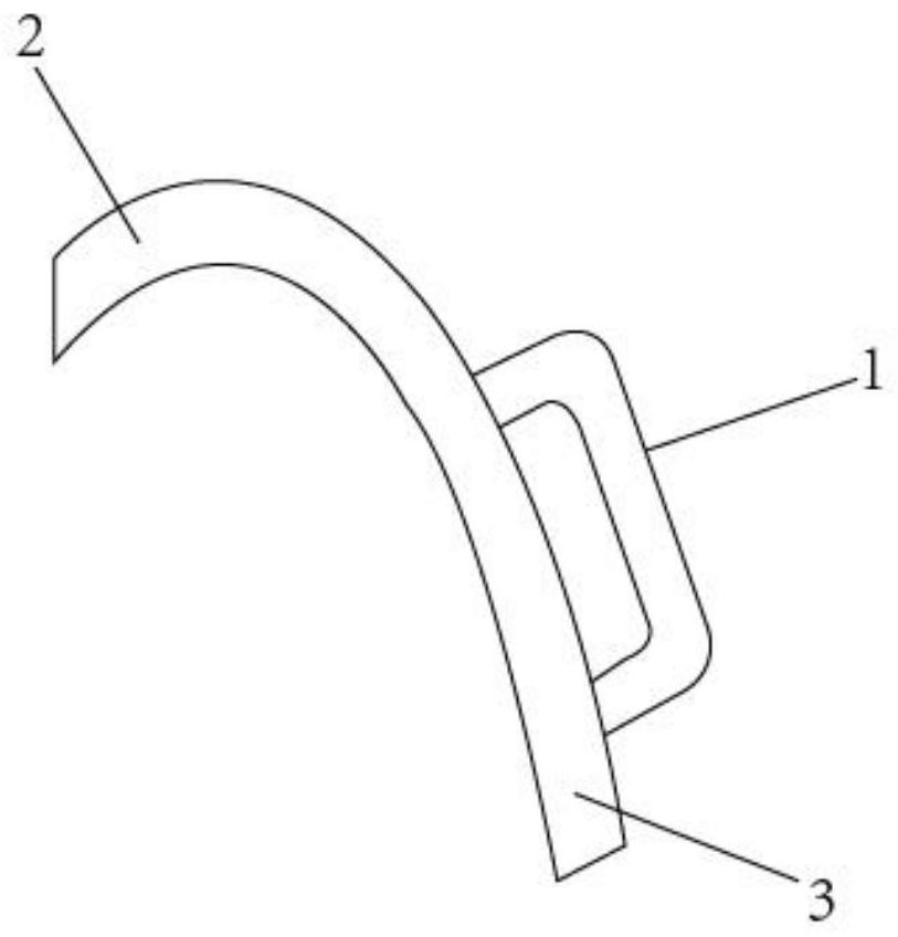
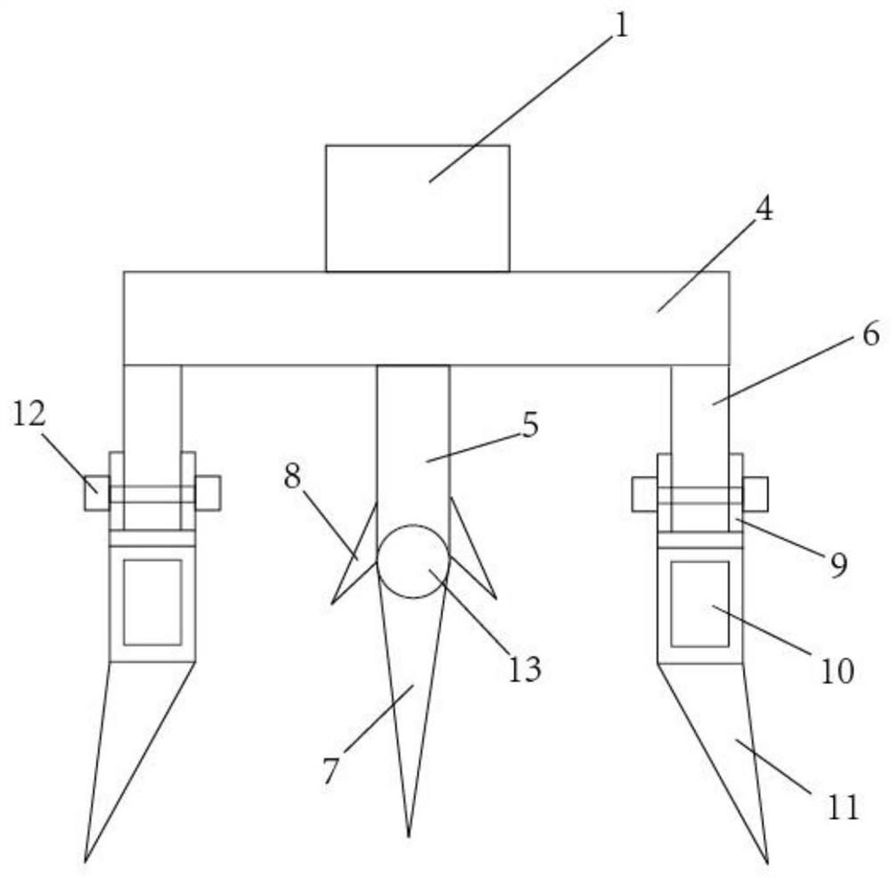
[0022] A device for trimming wind power blades, a handle, a first trimming part and a second trimming part, the first trimming part and the second trimming part are connected end to end, on the upper surface of the first trimming part and the second trimming part The handle is integrally set in the middle, the section structure of the first trimming part and the second trimming part is the same, both include the bottom plate, the blade mounting plate, the debris scraper mounting plate, the blade and the debris scraper, and the middle part is integrally set on the lower surface of the bottom plate The blade mounting plate is set, and the chip scraper mounting plate is respectively arranged on the lower surface of the bottom plate on both sides of the blade mounting plate, and the debris scraper is inserted into the chip scraper mounting plate, and a blade shaft is formed at the tail end of the blade mounting plate, and the blade The rotation is installed on the blade shaft, and ...

Embodiment 2

[0024] A device for trimming wind power blades, a handle, a first trimming part and a second trimming part, the first trimming part and the second trimming part are connected end to end, on the upper surface of the first trimming part and the second trimming part The handle is integrally set in the middle, the section structure of the first trimming part and the second trimming part is the same, both include the bottom plate, the blade mounting plate, the debris scraper mounting plate, the blade and the debris scraper, and the middle part is integrally set on the lower surface of the bottom plate The blade mounting plate is set, and the chip scraper mounting plate is respectively arranged on the lower surface of the bottom plate on both sides of the blade mounting plate, and the debris scraper is inserted into the chip scraper mounting plate, and a blade shaft is formed at the tail end of the blade mounting plate, and the blade The rotation is installed on the blade shaft, and ...

Embodiment 3

[0029] A device for trimming wind power blades, a handle, a first trimming part and a second trimming part, the first trimming part and the second trimming part are connected end to end, on the upper surface of the first trimming part and the second trimming part The handle is integrally set in the middle, the section structure of the first trimming part and the second trimming part is the same, both include the bottom plate, the blade mounting plate, the debris scraper mounting plate, the blade and the debris scraper, and the middle part is integrally set on the lower surface of the bottom plate The blade mounting plate is set, and the chip scraper mounting plate is respectively arranged on the lower surface of the bottom plate on both sides of the blade mounting plate, and the debris scraper is inserted into the chip scraper mounting plate, and a blade shaft is formed at the tail end of the blade mounting plate, and the blade The rotation is installed on the blade shaft, and ...


PUM

PropertyMeasurementUnit
heightaaaaaaaaaa
heightaaaaaaaaaa

Abstract

The invention provides a wind turbine vane shaping device. The wind turbine vane shaping device is characterized in that a first shaping part and a second shaping part are connected end to end, and a handle is integrally arranged in the middle of the upper surface of the first shaping part and the middle of the upper surface of the second shaping part; the section structures of the first shaping part and the second shaping part are the same and each comprise a bottom plate, a blade mounting plate, scrap scraper mounting plates, a blade and scrap scrapers; the blade mounting plate is integrally arranged in the middle of the lower surface of the bottom plate; the scrap scraper mounting plates are arranged on the lower surfaces of the portions, on the two sides of the blade mounting plate, of the bottom plate respectively, and the scrap scrapers are inserted into the scrap scraper mounting plates; a blade shaft is formed at the tail end of the blade mounting plate, and the blade is rotationally arranged on the blade shaft; and angle limiting plates are formed on the two sides of the blade shaft and used for limiting the maximum rotation angle of the blade. According to the wind turbine vane shaping device, scraps or powder can be scraped off along with shaping, and the blade can be adjusted by a certain angle along with the shaping direction.

Description

technical field [0001] The invention relates to the technical field of wind power generating devices, and more specifically relates to a device for repairing wind power blades. Background technique [0002] A wind turbine is a power device that converts wind energy into mechanical energy, which drives the rotor to rotate, and finally outputs alternating current. Once a problem occurs in the blades of the wind turbine, it will not only incur huge maintenance and replacement costs, but also affect the stability of the unit. There is a patent, patent number: 2019219186369, patent name: a new type of tooling for repairing the leading edge of wind turbine blades, which solves the problem that the existing repair requires the staff to operate with both hands, and the repair angle cannot be adjusted, but , the above-mentioned patents use the debris or powder generated after the repair to remain on the surface of the wind power blade, which is easy to affect the follow-up operation,...

Claims


Application Information

Patent Timeline
Patent Type & Authority Applications(China)
IPC IPC(8): B23P6/00B23Q3/06B23Q11/00B08B1/00
CPCB23P6/00B23Q3/06B23Q11/0042B08B1/165
Inventor 詹彪唐烂芳赵江王显义张锐
Owner 华能威宁风力发电有限公司
Learn More