
Automatic hook lifting walking robot for railway hump operation

A walking robot and robot technology, applied in the field of railway hooks, can solve the problems of limited space, difficulties in handling and transportation, and different speeds of trains and vehicles, and achieve the effects of fast speed and acceleration, reduced volume and weight, and large transmission power

Pending Publication Date: 2021-10-01
沈阳奇辉机器人应用技术有限公司
View PDF0 Cites 3 Cited by
  • Summary
  • Abstract
  • Description
  • Claims
  • Application Information

AI Technical Summary

Problems solved by technology

Some of the trains currently in use in marshalling yards in our country have been used for a long time, and the shackles have a certain amount of cargo damage, and the hook handle has a certain deformation, which makes it more difficult for the robot to automatically remove the hook.
[0007] 3. The speed of the train vehicle in operation does not vary
It is difficult to use robots instead of humans to unhook
[0009] 5. The number of train uncoupling sections is complex
This situation makes automatic unhooking have certain technical difficulties
[0010] 6. Space is relatively limited
[0011] 7. There is cover on the side of the coupler
It can only be used in power plants or mines where the number of vehicles is small and does not move
[0014] 2. Find the position of the coupler from the top of the carriage to lift the hook. If there is an outer edge of the carriage, the coupler of the carriage will be completely blocked, which may cause a collision between the overall equipment and the train carriage or fail to complete the hook lifting operation.
[0015] 3. It adopts double-track movement, driven by rack and pinion. Although it has good stability, it can be better used on moving carriages, but its volume is large, and it takes up a lot of space when used in marshalling stations, and the overall equipment The processing cost is relatively large, and it is difficult and costly to handle and transport
Very high installation and equipment costs

Method used


Image

  • Automatic hook lifting walking robot for railway hump operation
  • Automatic hook lifting walking robot for railway hump operation
  • Automatic hook lifting walking robot for railway hump operation

Examples


Embodiment Construction

[0039] The technical solutions in the embodiments of the present invention will be clearly and completely described below in conjunction with the accompanying drawings in the embodiments of the present invention. Obviously, the described embodiments are only some of the embodiments of the present invention, not all of them; based on The embodiments of the present invention and all other embodiments obtained by persons of ordinary skill in the art without making creative efforts belong to the protection scope of the present invention.

[0040] It should be noted that in this article, relational terms such as first and second are only used to distinguish one entity or operation from another entity or operation, and do not necessarily require or imply that there is a relationship between these entities or operations. There is no such actual relationship or order between them. Furthermore, the term "comprises", "comprises" or any other variation thereof is intended to cover a non-...


PUM


Abstract

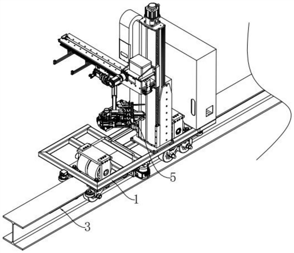
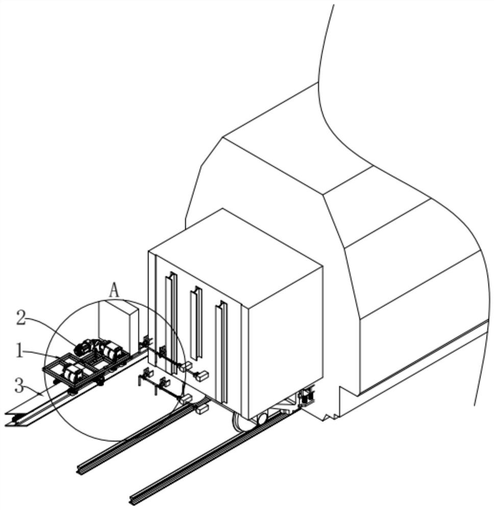
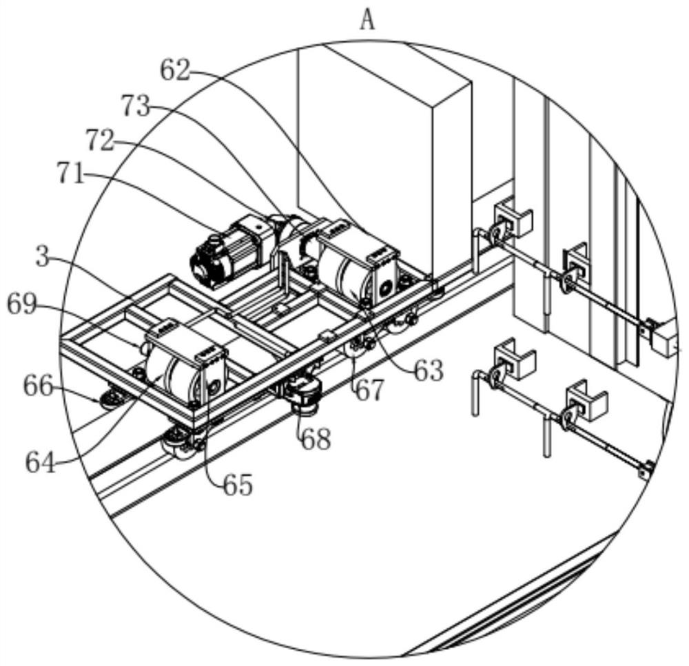
The invention discloses an automatic hook lifting walking robot for railway hump operation. The robot comprises a robot main body frame, a walking mechanism, an H-shaped steel rail, a two-axis movement mechanism and a hook lifting robot manipulator mechanism, the walking mechanism is arranged on the H-shaped steel rail, the robot main body frame is arranged on the walking mechanism, the two-axis movement mechanism is arranged on the robot main body frame, the two-axis movement mechanism is provided with a camera fixing plate, the hook lifting robot manipulator mechanism is arranged on the camera fixing plate, and the hook lifting robot manipulator mechanism comprises an overturning assembly, an oblique inserting assembly and a hook lifting assembly. The invention belongs to the technical field of railway lifting hooks, and particularly relates to a lifting mechanism which can stably walk on a rail, can achieve the same speed of a robot system and a train carriage, and can conduct two-axis movement on a lifting hook mechanical arm in a lifting hook robot system; and according to the automatic hook lifting walking robot for the railway hump operation, the whole hook lifting mechanical arm completes automatic hook lifting through a plurality of motors and mechanical mechanisms.

Description

technical field [0001] The invention belongs to the technical field of railway hook lifting, in particular to a walking robot for automatically lifting a hook for railway hump operations. Background technique [0002] At present, the hook lifting operations at the hump operation site of my country's railway marshalling stations are all done manually. The working process is as follows: the railway control room sends the car number and the corresponding section number to be decoded through the internal network, and then the hook lifter waits beside the peak road with the printed list. The row of carriages that need to be decomposed is pushed into the peak road by the locomotive, and the hook lifter begins to observe the car number of the corresponding carriage that needs to be operated by the hook at the corresponding position and needs to check whether the air duct under the carriage is removed. Then the hook lifter needs to follow the carriage to move, and then the person h...

Claims


Application Information

Patent Timeline
Patent Type & Authority Applications(China)
IPC IPC(8): B61G7/00
CPCB61G7/00
Inventor 张德华于旺邓平平王琛
Owner 沈阳奇辉机器人应用技术有限公司
Learn More