
Top plate joint cutting device and method

A roof and slit technology, which is applied in the direction of driving devices, earthwork drilling, cutting machinery, etc., can solve the problems of high transportation risk, difficulty in approval of explosives, and high danger

Inactive Publication Date: 2021-10-01
CHINA UNIV OF MINING & TECH (BEIJING)
View PDF9 Cites 0 Cited by
  • Summary
  • Abstract
  • Description
  • Claims
  • Application Information

AI Technical Summary

Problems solved by technology

The existing technology mainly adopts the method of explosive energy-concentrated blasting to directionally cut a crack surface in the roof rock mass, but the explosive explosive energy-concentrated blasting technology has difficulties in approval of explosives, high transportation risks, loud blasting noise, high risk, and harmful gas generation, etc. question

Method used


Image

  • Top plate joint cutting device and method
  • Top plate joint cutting device and method
  • Top plate joint cutting device and method

Examples


Embodiment Construction

[0040] Example embodiments will now be described more fully with reference to the accompanying drawings. Example embodiments may, however, be embodied in many forms and should not be construed as limited to the examples set forth herein; rather, these embodiments are provided so that this disclosure will be thorough and complete, and will fully convey the concept of example embodiments to those skilled in the art. The described features, structures, or characteristics may be combined in any suitable manner in one or more embodiments. In the following description, numerous specific details are provided in order to give a thorough understanding of embodiments of the present disclosure.

[0041] In the drawings, the thicknesses of regions and layers may be exaggerated for clarity. The same reference numerals in the drawings denote the same or similar structures, and thus their detailed descriptions will be omitted.

[0042] The described features, structures, or characteristic...


PUM


Abstract

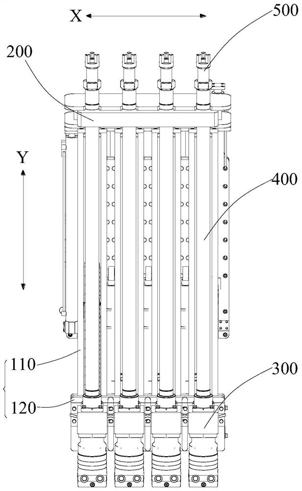
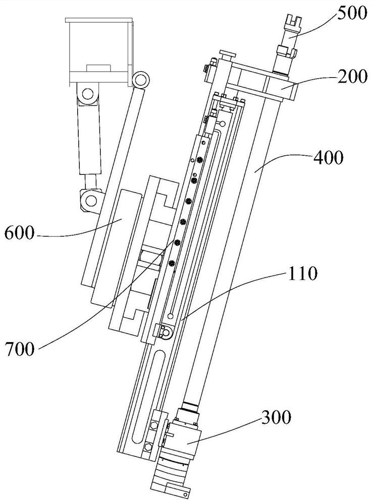
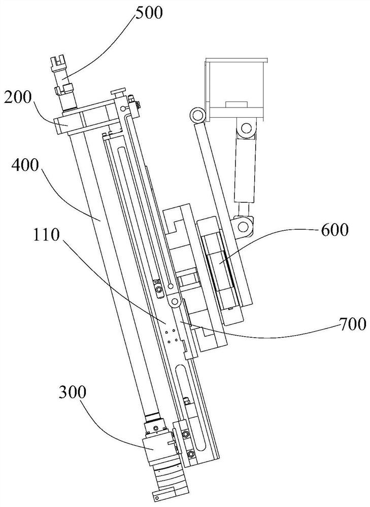
The invention provides a top plate joint cutting device and method, and belongs to the technical field of mining. The top plate joint cutting device comprises a supporting assembly, a first fixing plate, a plurality of drilling machines, a plurality of drilling rods and a plurality of drill bit assemblies, wherein the first fixing plate is fixed to one end of the supporting assembly; the multiple drilling machines are connected to the other end of the supporting assembly; the multiple drilling rods are located on one side of the supporting assembly, one ends of the drilling rods are detachably connected to the drilling machines, and the other ends of the drilling rods penetrate through the first fixing plate to be connected with the drill bit assemblies; and the multiple drill bit assemblies are arranged at equal intervals in the first direction, and the positions of the drill bit assemblies, the positions of the drilling rods and the positions of the drilling machines are in one-to-one correspondence. According to the top plate joint cutting device and method, the multiple drill bit assemblies are arranged, the distances between the drill bit assemblies are equal, therefore, dense drilling can be achieved through multiple times of drilling, and thus top plate joint cutting operation can be completed without explosive blasting.

Description

technical field [0001] The present disclosure relates to the technical field of mining, in particular to a roof cutting device and method. Background technique [0002] In underground coal mining, the roof directional slitting technology is one of the key core technologies for self-forming roadway mining without coal pillars. The existing technology mainly adopts the method of explosive energy-concentrated blasting to cut a crack surface in the direction of the roof rock mass, but the explosive explosive energy-concentrated blasting technology has difficulty in approval of explosives, high transportation risk, loud blasting noise, high risk, and harmful gas generation, etc. question. Therefore, it is necessary to find new equipment and technology to complete roof cutting while reducing safety risks. [0003] The above information disclosed in this Background section is only for enhancement of understanding of the background of the disclosure and therefore it may contain in...

Claims


Application Information

Patent Timeline
Patent Type & Authority Applications(China)
IPC IPC(8): E21C27/02E21C31/02E21C35/00
CPCE21C27/02E21C31/02E21C35/00
Inventor 杨军王亚军闵铁军何满潮王琦刘辉陈菲
Owner CHINA UNIV OF MINING & TECH (BEIJING)
Learn More