Floor pipeline damping device
A shock absorption device and pipeline technology, applied in the direction of pipes, pipe elements, pipes/pipe joints/pipe fittings, etc., can solve the problems of inconvenient pre-embedding of expansion bolts, poor shock absorption capacity, and poor installation firmness.
- Summary
- Abstract
- Description
- Claims
- Application Information
AI Technical Summary
Problems solved by technology
Method used
Image

Examples
Embodiment Construction
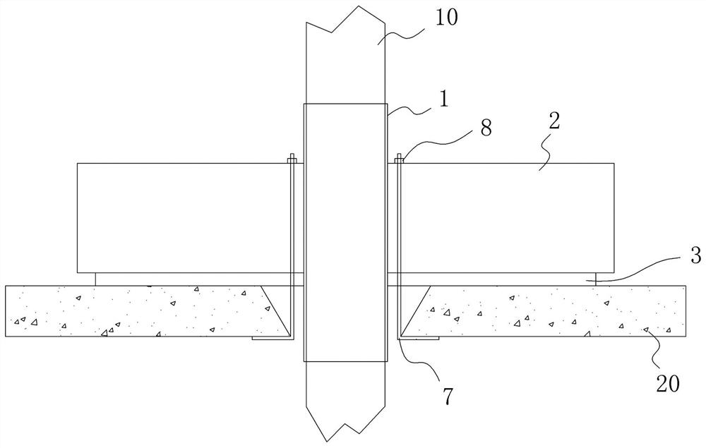
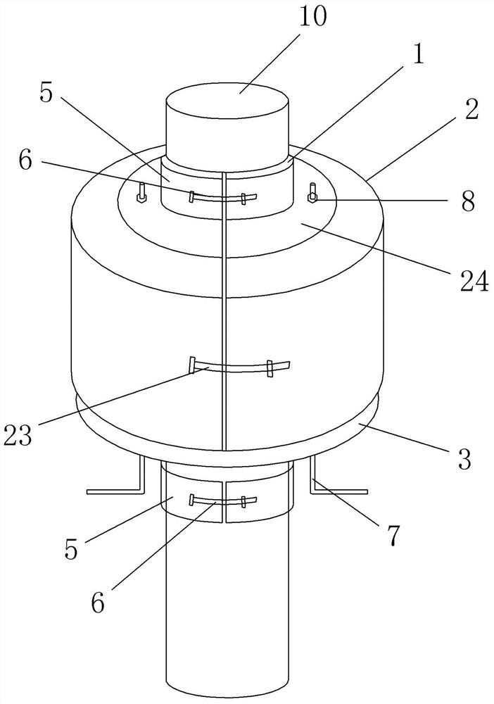
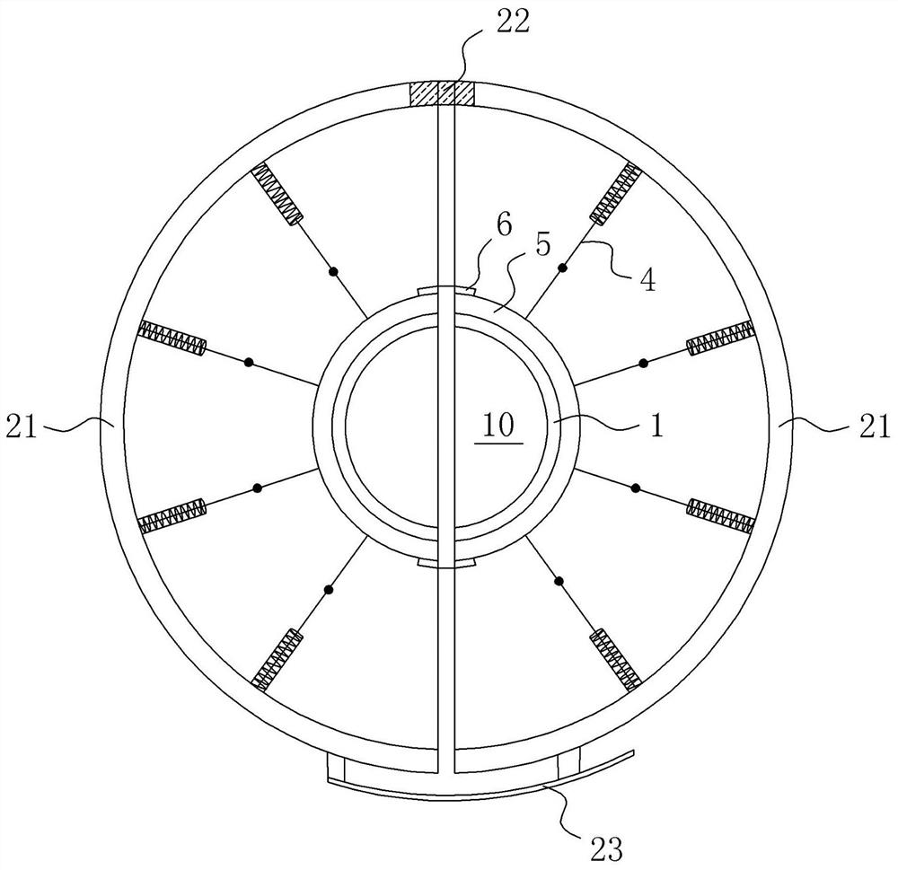
[0010] A floor pipeline damping device, comprising a pipe cushion 1 set outside the pipeline, the two ends of the pipeline respectively extend to both sides of the floor and fixed on the pipeline through fastening components, a shell 2 is provided on one side of the floor, and the shell Covering the outside of the pipe pad and having a bottom pad 3 between the floor and a fixing assembly for fixing the shell and the bottom pad on the floor; several spring groups are installed between the shell and the pipe pad along the circumference of the pipe, each Each spring group includes two spring shock absorbers 4 that are symmetrically arranged along the horizontal direction and inclined.
[0011] In the above-mentioned floor pipeline damping device, the shell 2 includes two shells 21 that are arranged opposite to each other and form a ring shape. The opposite ends of the two shells are connected to each other through locking components, so as to facilitate the installation or disasse...
PUM
 Abstract
Description
Claims
Application Information
 - R&D
- Intellectual Property
- Life Sciences
- Materials
- Tech Scout
- Unparalleled Data Quality
- Higher Quality Content
- 60% Fewer Hallucinations
Browse by: Latest US Patents, China's latest patents, Technical Efficacy Thesaurus, Application Domain, Technology Topic, Popular Technical Reports.
© 2025 PatSnap. All rights reserved.Legal|Privacy policy|Modern Slavery Act Transparency Statement|Sitemap|About US| Contact US: help@patsnap.com