
A kind of dynamic drying equipment for powdery plastic particles

A technology of plastic particles and drying equipment, which is applied in the direction of non-progressive dryers, drying solid materials, drying chambers/containers, etc., can solve the problems of low drying efficiency and drying uniformity, and achieve improved drying uniformity and improved drying efficiency. efficiency effect

Active Publication Date: 2021-11-02
HAIMEN JINQILIN REDWOOD INVESTMENT DEV
View PDF5 Cites 0 Cited by
  • Summary
  • Abstract
  • Description
  • Claims
  • Application Information

AI Technical Summary

Problems solved by technology

[0003] In the prior art, when the plastic particles are dried, the drying is generally carried out by rotating and cooperating with hot air. Although the rotation makes the plastic particles relatively dispersed, due to the centrifugal force, most of the particles still gather together under the action of rotation, resulting in Drying efficiency and drying uniformity are still not high

Method used


Image

  • A kind of dynamic drying equipment for powdery plastic particles
  • A kind of dynamic drying equipment for powdery plastic particles
  • A kind of dynamic drying equipment for powdery plastic particles

Examples


Embodiment 1

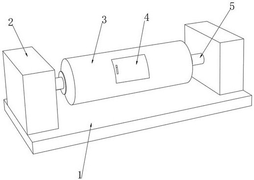
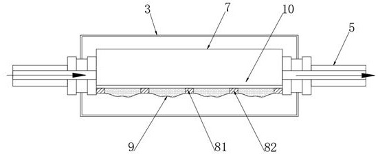
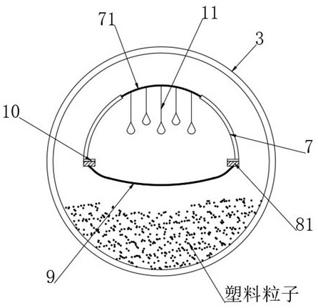
[0041] see figure 1 , a dynamic drying equipment for powder-topping plastic particles, comprising a bottom plate 1, air boxes 2 are fixedly connected to the left and right ends of the bottom plate 1, a blower is installed in one air box 2, and an exhaust fan is connected in the other air box 2, and The air box 2 equipped with a blower communicates with the external hot air source, and the other air box 2 has an air outlet. Through the blower and exhaust fan, the circulation of the hot air in the outer drum 3 is effectively realized, so that the outer drum 3 is taken away in time The water vapor separated from the plastic particles by heating inside makes the drying effect better. The ends of the two air boxes 2 close to each other are fixedly connected with the rotating shaft 5. The rotating shaft 5 is a hollow structure, and the rotating shaft 5 communicates with the air box 2 and the outer drum 3. , and the inner wall of the end of the rotating shaft 5 located in the outer r...

Embodiment 2

[0047] see Figure 9 , the powder-passing layer 71 is a high-toughness structure provided with a plurality of parallel strip-shaped holes. The moving rod 11 is constantly subjected to downward attraction at intervals, and the distances between the plurality of longitudinal moving rods 11 and the traction rod 82 are different, so that the force is different, so that the left and right long edges of the strip-shaped hole are vertically aligned. Offset from each other to make the gap larger and further ensure the falling of plastic particles.

[0048] This embodiment remains the same as that of Embodiment 1 except that the over-powder layer 71 is different from Embodiment 1.


PUM


Abstract

The invention discloses a powder-turning dynamic drying equipment for plastic particles, which belongs to the field of drying equipment. The powder-turning dynamic drying equipment for plastic particles is equipped with a powder-turning clutch bag to dry some plastic particles while rotating. After reaching the top under the action of centrifugal force, part of it enters the inner fixed cylinder and falls into the top powder clutch bag. When multiple electromagnetic plates are energized at intervals, the driving bar is pulled to reciprocate, so that the end of the top powder bag first The plastic particles are close to each other so that the plastic particles gather in the middle, and then they are quickly stretched and straightened, thereby generating a large bumping force on the plastic particles on it, and the plastic particles are quickly dispersed upwards and fully contacted with the hot air. In a bumpy dynamic, compared with the existing technology, the drying efficiency and drying uniformity are significantly improved, and when the traction bar moves back and forth, the multiple longitudinal rods are constantly stressed at intervals, effectively accelerating the plastic particles into the inner fixed cylinder Inside.

Description

technical field [0001] The invention relates to the field of drying equipment, more specifically, to a dynamic drying equipment for powder-topping plastic particles. Background technique [0002] In order to improve the quality of plastic products, their raw materials are generally processed into plastic masterbatches. Loose plastic masterbatches are prone to moisture when exposed to air. The chemical properties of plastic products made of damp plastic raw materials will be significantly reduced, which will affect the quality of the product. Therefore, the loose plastic masterbatch needs to be dried before being processed into plastic products. The common method is to use the fan to pass the heat of the heater through The pipe feeds directly into a pile of loose material where it is dried. [0003] In the prior art, when plastic particles are dried, they are generally dried by rotating and introducing hot air. Although the rotation makes the plastic particles relatively di...

Claims


Application Information

Patent Timeline
Patent Type & Authority Patents(China)
IPC IPC(8): F26B11/04F26B21/00F26B25/02F26B25/16
CPCF26B11/04F26B21/001F26B21/004F26B25/02F26B25/16
Inventor 茅正芳
Owner HAIMEN JINQILIN REDWOOD INVESTMENT DEV
Learn More