
Co-location MIMO radar multi-target tracking resource optimal allocation method for angular glint noise scene

A multi-target tracking and resource optimization technology, which is applied in the field of optimal allocation of multi-target tracking resources for co-site MIMO radars, can solve the problems of in-depth research on optimal allocation of unlaunched resources, inability to accurately reflect target tracking performance, and increased tracking difficulty. Meet the requirements of ensuring stability and timeliness, improve tracking accuracy and stability, and improve convergence performance

Active Publication Date: 2021-10-01
AIR FORCE UNIV PLA
View PDF5 Cites 5 Cited by
  • Summary
  • Abstract
  • Description
  • Claims
  • Application Information

AI Technical Summary

Problems solved by technology

Under angular flicker noise, radar resource allocation tasks face greater challenges due to the increased tracking difficulty
[0003] There are some deficiencies in the existing research on MIMO radar resource allocation: ① Existing literature focuses on the configuration of transmit power, and does not conduct in-depth research on the optimal allocation of other transmit resources including effective bandwidth; ② Existing resources Most of the allocation research is carried out under ideal Gaussian noise, while the actual measurement noise is often non-Gaussian; ③The existing optimization index used to guide the allocation of target tracking resources is usually PCRLB, and PCRLB is not associated with the current measurement information, and cannot Accurately reflects object tracking performance under non-ideal conditions

Method used


Image

  • Co-location MIMO radar multi-target tracking resource optimal allocation method for angular glint noise scene
  • Co-location MIMO radar multi-target tracking resource optimal allocation method for angular glint noise scene
  • Co-location MIMO radar multi-target tracking resource optimal allocation method for angular glint noise scene

Examples


Embodiment Construction

[0086] In order to make the purpose, technical solutions and advantages of the embodiments of the present invention clearer, the technical solutions in the embodiments of the present invention will be clearly and completely described below in conjunction with the drawings in the embodiments of the present invention. Obviously, the described embodiments It is a part of embodiments of the present invention, but not all embodiments. The components of the embodiments of the invention generally described and illustrated in the figures herein may be arranged and designed in a variety of different configurations.

[0087] Accordingly, the following detailed description of the embodiments of the invention provided in the accompanying drawings is not intended to limit the scope of the claimed invention, but merely represents selected embodiments of the invention. Based on the embodiments of the present invention, all other embodiments obtained by persons of ordinary skill in the art wi...


PUM


Abstract

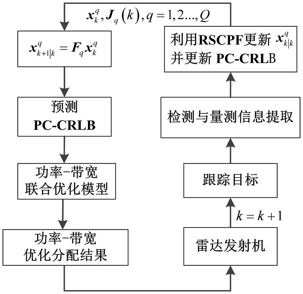
The invention discloses a co-location MIMO radar multi-target tracking resource optimal allocation method for an angular glint noise scene. The method comprises the following steps of: 1, estimating the motion state of a target through employing a robust square root volume particle filtering algorithm according to the characteristics of angular glint noise; 2, predicting PC-CRLB at the next moment according to target motion state estimation information, and constructing a non-convex optimization model about power and broadband joint allocation, namely a power-bandwidth joint optimization model; and 3, converting the non-convex optimization model into a convex optimization model by using a convex relaxation and cyclic minimization method, solving the convex optimization model through an SDP algorithm and a Frank-Wolfe algorithm, and finally feeding back a solving result to a radar transmitter to guide resource allocation in a target tracking process at the next moment, and thus, constructing a co-location MIMO radar transmission resource adaptive allocation mechanism. The algorithm provided by the invention can completely ensure the stability and timeliness requirements of a resource allocation task.

Description

technical field [0001] The invention belongs to the technical field of resource optimization allocation, and in particular relates to a method for optimal allocation of co-site MIMO radar multi-target tracking resources facing an angular flicker noise scene. Background technique [0002] Co-located multiple-input and multiple-output (MIMO) radar has good waveform diversity gain, which can effectively detect and track weak targets. In recent years, it has become an important topic in the field of MIMO radar resource allocation to establish a closed-loop feedback loop between the receiver and the transmitter in combination with cognitive radar technology to realize adaptive allocation of transmission resources. When the radar tracks complex extended targets such as airplanes and ships, the interaction between different phase scattering points will lead to distortion of the phase of the received echo and angular scintillation. Angular flicker noise is the inherent angle measur...

Claims


Application Information

Patent Timeline
Patent Type & Authority Applications(China)
IPC IPC(8): G01S13/72G06F17/16
CPCG01S13/726G06F17/16
Inventor 李正杰谢军伟邵雷李媛齐铖张浩为葛佳昂刘宇璇
Owner AIR FORCE UNIV PLA
Learn More