


Quick Research
Generate reliable direction feasibility study reports for your R&D in just a few steps.

Technical Q&A
Discover and master advanced knowledge NOW. Basics, ideas, possibilities, all at once.

Find Solutions
As an expert in R&D theories, this can generate solutions to your technical problems instantly.

Evaluate Feasibility
Analyze your overall solution with one click, know your potential R&D risks in advance.

Monitor Landscape
Get weekly tech updates, stay abreast of the latest tech innovations and key insights.
A self-adjusting built-in embedded joint and its embedded method
A self-adjusting and pre-embedded technology, applied in vibration suppression adjustment, spring/shock absorber, cable installation, etc., can solve problems such as easy displacement of pre-embedded joints, pre-embedded joint instability, inconvenient maintenance, etc., to achieve The splicing structure is novel and ingenious, reducing the probability of maintenance and prolonging the service life
- Summary
- Abstract
- Description
- Claims
- Application Information
AI Technical Summary
Problems solved by technology
Method used
Image

Examples
Embodiment 1
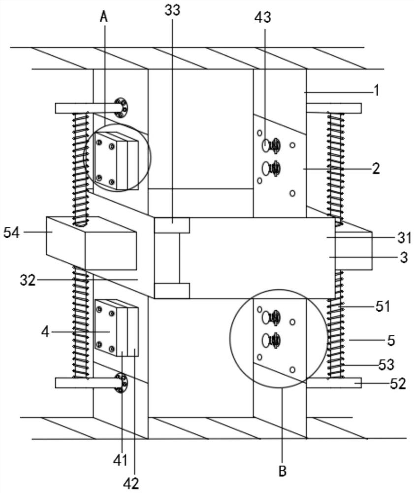
[0047] Refer to the manual attached Figure 1-9 , a self-adjusting building embedded section of this embodiment includes a bridge 1, the bridge 1 is provided with a second through hole 11, and also includes: a butt plate 2 detachably connected to the bridge 1; and
[0048] The embedded section 3 of the detachable connecting bridge;
[0049] The bridge frame 1 and the docking plate 2 are connected through the first connection assembly 4, and the bridge frame 1 and the embedded section 3 are connected through the second connection assembly 5 or the fourth connection assembly 6;
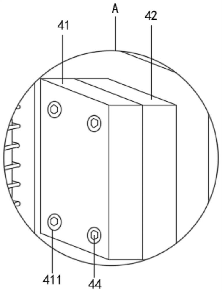
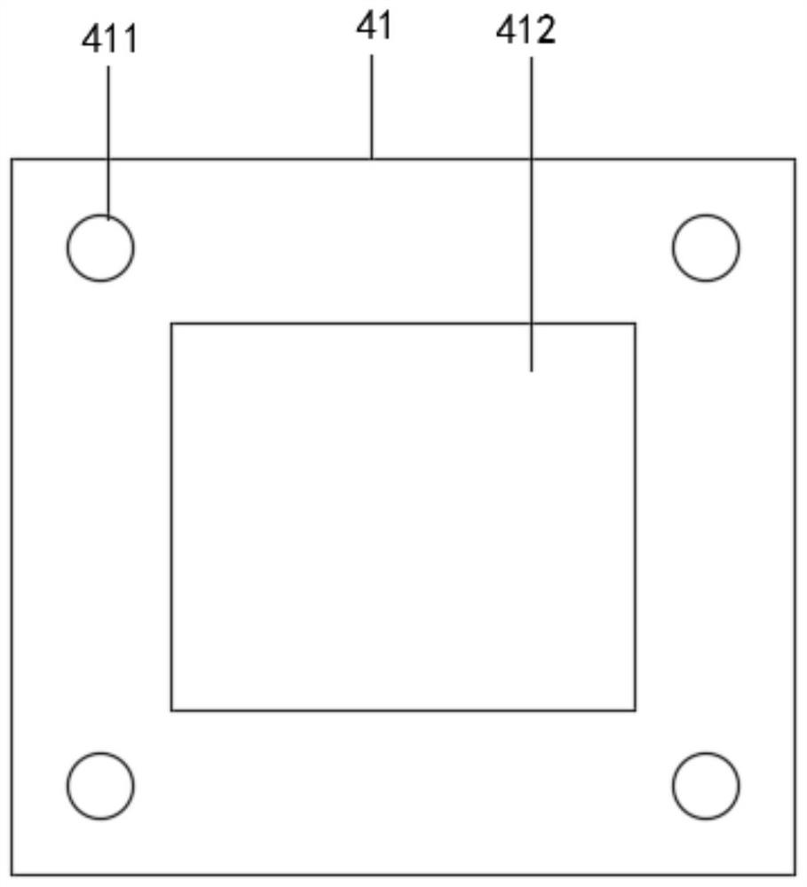
[0050] The first connecting assembly 4 includes a first square plate 41, the first square plate 41 is connected to the second square plate 42, and the second square plate 42 is provided with a first through hole 422, a first rectangular through hole 423 and a rectangular groove 424, the inner wall of the first through hole 422 is inserted into the pin 43;
[0051] The plug 43 includes an insertion rod...
Embodiment 2
[0067] Refer to the manual attached Figure 10-11 , and the difference from Embodiment 1 is: the bridge frame 1 and the embedded section 3 are connected through the fourth connecting component 6;
[0068] The fourth connecting assembly 6 includes a sliding seat 61, and the inner wall of the embedded joint 3 is fixedly installed with a sliding seat 61. The sliding seat 61 is provided with a T-shaped sliding groove 611, and the inner wall of the T-shaped sliding groove 611 is slidably connected to the T-shaped sliding seat 61. One end of the T-shaped sliding block 21 is fixedly connected to the docking plate 2 , the two ends of the sliding seat 61 are fixedly connected to the cover 62 by bolts, and a fourth spring 63 is arranged in the T-shaped sliding groove 611 , one end of the fourth spring 63 is fixedly connected to the cover 62, and the other end of the fourth spring 63 is fixedly connected to the T-shaped slider 21;
[0069] The implementation scenarios are as follows:
...
PUM
 Abstract
Description
Claims
Application Information
 - R&D Engineer
- R&D Manager
- IP Professional
- Industry Leading Data Capabilities
- Powerful AI technology
- Patent DNA Extraction
Browse by: Latest US Patents, China's latest patents, Technical Efficacy Thesaurus, Application Domain, Technology Topic, Popular Technical Reports.
© 2024 PatSnap. All rights reserved.Legal|Privacy policy|Modern Slavery Act Transparency Statement|Sitemap|About US| Contact US: help@patsnap.com