
27.5 kV semi-rigid thermal shrinkage cable terminal for high-speed rail

A heat-shrinkable cable and semi-rigid technology, which is applied in the installation of cable terminals, cable accessories, and cables, can solve the problems of cable terminal breakdown, accelerated deterioration, and increased discharge, and achieve enhanced insulation protection and improved weather resistance , Increase the effect of creepage distance

Active Publication Date: 2021-10-01
中科英华长春高技术有限公司
View PDF12 Cites 0 Cited by
  • Summary
  • Abstract
  • Description
  • Claims
  • Application Information

AI Technical Summary

Problems solved by technology

Combined with the analysis of typical accident cases in recent years, it can be seen that the design of the 27.5kV high-voltage cable terminals in use cannot meet the needs of the high-speed rail operating environment. , cable terminals with a designed service life of 20 years often have partial discharge increases or even breakdown accidents in less than 2 years, resulting in delays for trains preparing to depart, and even breakdowns of cable terminals on running high-speed railways. Emergency braking causes major operational accidents
[0004] Chinese patent CN103532081 A discloses a high-voltage cable terminal for EMUs. The electrical clearance and creepage distance of the high-voltage cable terminal designed by this patent cannot meet the requirements of national standards, and the casing material (epoxy resin or glass fiber reinforced plastic) used has poor weather resistance. Unable to apply to EMU body traction power supply jumper power supply system

Method used


Image

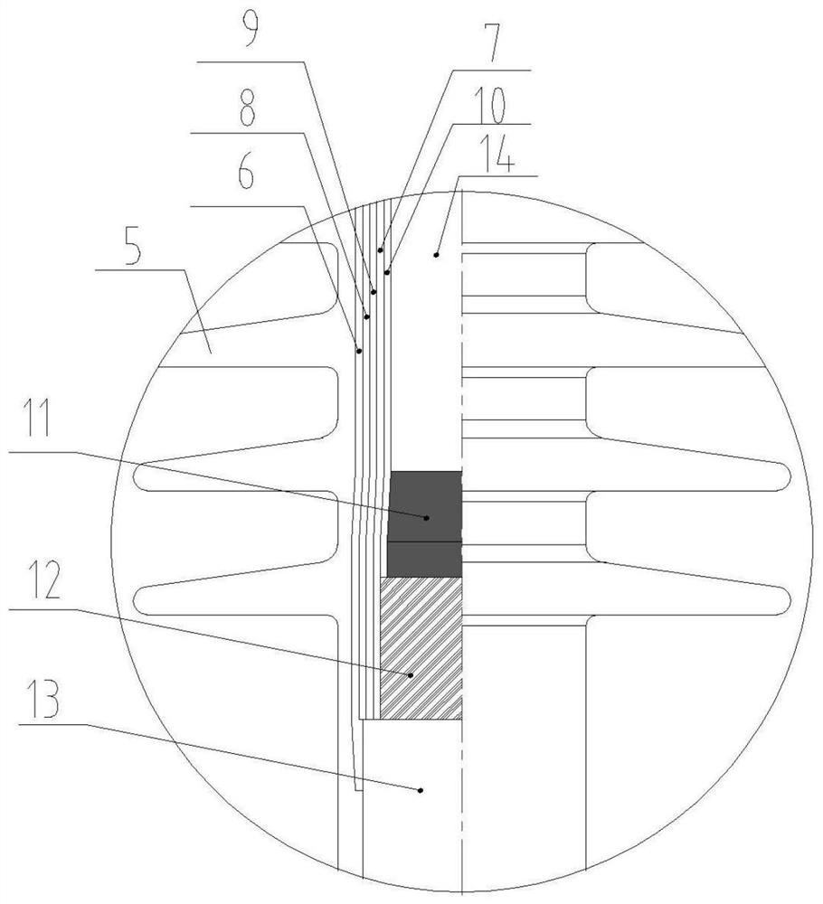
  • 27.5 kV semi-rigid thermal shrinkage cable terminal for high-speed rail
  • 27.5 kV semi-rigid thermal shrinkage cable terminal for high-speed rail

Examples


Embodiment Construction

[0024] In order to make the technical problems, technical solutions and beneficial effects to be solved by the present invention clearer, the present invention will be further described in detail below in conjunction with the accompanying drawings and embodiments. It should be understood that the specific embodiments described here are only used to explain the present invention, not to limit the present invention.

[0025] It should be noted that when a component is referred to as being “fixed on” or “disposed on” another component, it may be directly or indirectly located on the other component. When an element is referred to as being "connected to" another element, it can be directly or indirectly connected to the other element. The terms "upper", "lower", "left", "right", "front", "rear", "vertical", "horizontal", "top", "bottom", "inner", "outer", etc. The indicated orientation or position is based on the orientation or position shown in the drawings, and is only for conv...


PUM

PropertyMeasurementUnit
distanceaaaaaaaaaa

Abstract

The invention relates to the technical field of cable accessories, and provides a 27.5 kV semi-rigid thermal shrinkage cable terminal for a high-speed rail. The terminal comprises a cable sheath layer, a cable shielding layer exposed by stripping the cable sheath layer, a cable semi-conductive layer exposed by stripping the cable shielding layer, and a cable insulating layer exposed by stripping the cable semi-conductive layer. A stress tube is arranged on the peripheries of the cable insulating layer and the cable semi-conductive layer, an insulating tube I is arranged on the peripheries of the stress tube and the cable shielding layer, a nonlinear resistance tube is arranged on the periphery of the insulating tube I, an insulating tube II is arranged on the periphery of the nonlinear resistance tube, and a glass fiber curing layer is arranged on the periphery of the insulating tube II. The terminal has the advantages that the stress tube, the insulating tube I, the non-linear resistance tube and the insulating tube II form a composite insulation structure, and breakdown accidents caused by increase of partial discharge can be effectively avoided; and the glass fiber curing layer forms a stress control reinforcing band so that the thermal shrinkage cable terminal obtains relatively high rigidity and is effectively prevented from being influenced by high-frequency vibration.

Description

technical field [0001] The invention relates to the technical field of cable accessories, in particular to a 27.5kV semi-rigid heat-shrinkable cable terminal for high-speed rail. Background technique [0002] Heat-shrinkable cable accessories are widely used in various important occasions of power transmission. Because heat-shrinkable cable accessories have key characteristics such as light weight, small size, and high hardness, they have wider applications than cold-shrinkable cable accessories, such as: nuclear power plant nuclear island, conventional Island, high-speed train top power supply, etc. [0003] At present, most of the 27.5kV high-voltage cable terminals in use on the high-speed rail are heat-shrinkable terminals imported from Raychem in the United States, and their reliability has been severely tested during the operation of the high-speed rail. Combined with the analysis of typical accident cases in recent years, it can be seen that the design of the 27.5kV ...

Claims


Application Information

Patent Timeline
Patent Type & Authority Applications(China)
IPC IPC(8): H02G15/06H02G15/064
CPCH02G15/06H02G15/064
Inventor 李小军金文斌左明洁张佳乐王婷婷陈富刘正威张婧妍蒋鹏李赫
Owner 中科英华长春高技术有限公司
Learn More