

Circuit board pressing method
A circuit board and connecting board technology, which is applied in the field of circuit board pressing, can solve the problems of reducing the service life of the oil cylinder, difficulty in feeding, reducing the quality and effect of pressing, and achieves reduction of deformation and warping, good pressing effect and quality. improved effect
- Summary
- Abstract
- Description
- Claims
- Application Information
AI Technical Summary
Problems solved by technology
Method used
Image

Examples
Embodiment 1
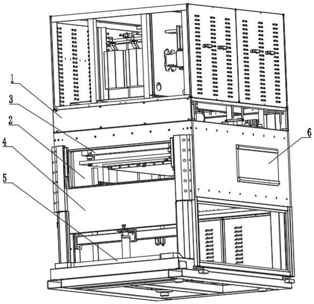
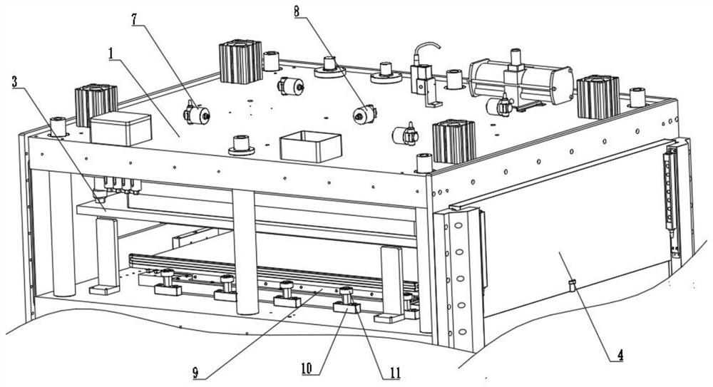
[0038] A circuit board pressing method, such as Figure 1-Figure 5As shown, including the body 1, the interior of the body 1 is provided with a cavity 2 for pressing the circuit board up and down, the cavity 2 is provided with a pressing mechanism 3 for pressing, and the front part of the body 1 is provided with a pair of cavity 2 The sealing mechanism 4 for sealing, the bottom of the body 1 is fixedly connected with the base 5, the inside of the body 1 is provided with a limit auxiliary mechanism 9 for auxiliary positioning of the circuit board, and the inside of the body 1 is fixedly installed with a pressure relief valve 7 and an inflation valve 8 ;
[0039] A circuit board pressing method comprises the following steps:
[0040] Step 1: Feeding, the operator pushes the stacked circuit boards from the position of the material inlet to the pressing table;
[0041] Step 2: seal, then the oil cylinder 41 is extended, and the airtight door 42 is controlled to rise and move. Wh...
Embodiment 2
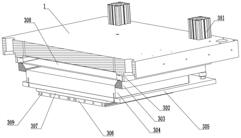
[0054] Such as Figure 6 As shown, the limit auxiliary mechanism 9 includes a connection block 93, the surface of the connection block 93 is connected with an upper support plate 91 and a lower support plate 92 by bolts, the connection block 93 is fixedly connected with an inflation nozzle 96, the upper support plate 91 and the lower support plate Air bag bar three 95 is arranged in the cavity that support plate 92 forms, and the end of air bag bar three 95 is fixedly connected on the lower support plate 92 by bolts, and the upper support plate 91 is slidably connected with sliding connecting plate 97, and the limit of setting Auxiliary mechanism 9 makes the process of pushing the circuit board more convenient, fast, and more labor-saving, and after the inflation and deflation of the air bag strip 3 95, the position of the circuit board can be placed, avoiding manual handling Finding a location is time-consuming and labor-intensive.
[0055] In this embodiment, several push b...
PUM
 Abstract
Description
Claims
Application Information