
Non-contact ophthalmic optical measuring scale

An optical measurement, non-contact technology, applied in applications, medical science, equipment for testing eyes, etc., can solve problems that affect the accuracy of measurement, eye infection, damage to eye structures, etc.

Pending Publication Date: 2021-10-08
WENZHOU MEDICAL UNIV
View PDF0 Cites 0 Cited by
  • Summary
  • Abstract
  • Description
  • Claims
  • Application Information

AI Technical Summary

Problems solved by technology

[0002] Existing ophthalmic measuring rulers or measuring gauges are all physical measuring devices with scales. When measuring, they need to be as close as possible to the measured object to complete the comparison measurement. The existence of parallax and the fact that the measuring ruler or gauge is not on the same plane as the measured object may affect the accuracy of the measurement. Therefore, in order to accurately measure some ocular surface structures clinically, such as the diameter of the cornea, the size of the conjunctival tumor, and the range of corneal opacity, it is necessary to Spot anesthesia on the surface of the eye, and make the measuring ruler or measuring gauge touch the object to be measured to complete the comparison measurement. It is an invasive measurement. If the operation is not done properly, there is a risk of damaging the ocular structure or causing eye infection. At the same time, the ocular surface Use of narcotics also increases medical costs and eye irritation

Method used


Image

  • Non-contact ophthalmic optical measuring scale
  • Non-contact ophthalmic optical measuring scale
  • Non-contact ophthalmic optical measuring scale

Examples


Embodiment Construction

[0022] The technical solutions in the embodiments of the present invention will be clearly and completely described below in conjunction with the accompanying drawings in the embodiments of the present invention. Obviously, the described embodiments are only part of the embodiments of the present invention, not all of them. Based on the embodiments of the present invention, all other embodiments obtained by persons of ordinary skill in the art without creative efforts fall within the protection scope of the present invention.

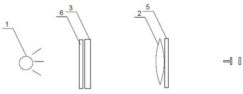
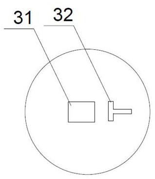
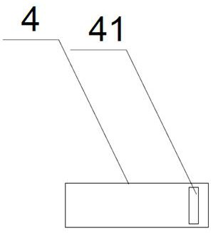
[0023] A non-contact ophthalmic optical measuring ruler, comprising a light source 1, one side of the light source 1 is provided with a convex lens 2, and a first shading plate 3 is provided between one side of the convex lens 2 and the light source 1, the A strip-shaped measuring hole 31 and a positioning light slit 32 are horizontally provided on the first light-shielding plate 3, and a strip-shaped light-shielding sheet 4 is arranged on the first ligh...


PUM

PropertyMeasurementUnit
Lengthaaaaaaaaaa

Abstract

A non-contact ophthalmic optical measuring scale comprises a light source; a convex lens is arranged on one side of the light source; a first light shielding plate is arranged between one side of the convex lens and the light source; a strip-shaped measuring hole and a positioning light seam are horizontally formed in the light shielding plate; a strip-shaped light shielding piece is arranged on the first light shielding plate; the light shading piece is arranged on the measuring hole and is in relative movable fit with the first light shading plate; a measuring light seam is formed in the light shading piece; a second light shading plate is arranged on the other side of the convex lens; two image dividing holes are longitudinally formed in the second light shading plate; and the two image dividing holes are perpendicular to the measuring hole and the positioning light seam in position. According to the non-contact ophthalmic optical measuring scale, an optical measurement mark is projected on a measured object according to an optical imaging principle, and comparison measurement on a same plane is completed, which aims to complete measurement of an eye structure in a non-contact state, so that eye stimulation to an examinee is reduced and the risk that the eye structure is damaged and eye infection is caused due to contact measurement is eliminated.

Description

technical field [0001] The invention specifically relates to the technical field of eye-use auxiliary measurement, in particular to a non-contact eye-use optical measuring ruler. Background technique [0002] Existing ophthalmic measuring rulers or measuring gauges are all physical measuring devices with scales. When measuring, they need to be as close as possible to the measured object to complete the comparison measurement. The existence of parallax and the fact that the measuring ruler or gauge is not on the same plane as the measured object may affect the accuracy of the measurement. Therefore, in order to accurately measure some ocular surface structures clinically, such as the diameter of the cornea, the size of the conjunctival tumor, and the range of corneal opacity, it is necessary to Spot anesthesia on the surface of the eye, and make the measuring ruler or measuring gauge touch the object to be measured to complete the comparison measurement. It is an invasive mea...

Claims


Application Information

Patent Timeline
IPC IPC(8): A61B3/10
CPCA61B3/0008A61B3/1005
Inventor 潘安鹏俞阿勇陈思韵
Owner WENZHOU MEDICAL UNIV
Learn More