
Metal steel plate end face chip milling device

A face milling and steel plate technology, which is applied in the direction of positioning devices, metal processing equipment, metal processing machinery parts, etc., can solve the problems of high plane precision requirements, difficult processing of the processing area, uncontrollable plane precision, etc., and achieve compact structure, Accurate brightness size and strong self-inspection ability

Pending Publication Date: 2021-10-08
潘炳汉
View PDF0 Cites 0 Cited by
  • Summary
  • Abstract
  • Description
  • Claims
  • Application Information

AI Technical Summary

Problems solved by technology

[0002] Steel processing needs to process six faces, and the upper and lower end faces are generally called planes. The plane processing area is the largest and the most difficult to process. The reason is that there is an oxide layer on it. In the past, ordinary gantry milling or powerful milling was used for processing. End milling, a powerful disk is installed on the machine tool. This kind of machine tool has a milling head with a cutter head. Rough milling and fine milling are also a cutter head. The up and down, forward, and left and right of the machine tool are manually operated. This manual machine tool has no CNC Driven by the setting value of the machine, the height of the steel must be uniform before it can be processed. If the plane height is different, it cannot be processed. The disadvantage is that the quality of the processed steel plate is poor. Because the plane accuracy is uncontrollable, many processing plants have to do one more process, and take the workpiece to the grinding machine for fine grinding. Moreover, when processing in traditional processing plants, they cannot be divided into multiple processing areas. The steel plate needs to be processed at the same height, with one spindle design, the rough and fine cutters are the same, the control accuracy is poor, and basically there is no protection for the equipment

Method used


Image

  • Metal steel plate end face chip milling device
  • Metal steel plate end face chip milling device
  • Metal steel plate end face chip milling device

Examples


Embodiment Construction

[0025] The technical solutions of the present invention will be clearly and completely described below in conjunction with the accompanying drawings. Apparently, the described embodiments are some of the embodiments of the present invention, but not all of them. Based on the embodiments of the present invention, all other embodiments obtained by persons of ordinary skill in the art without making creative efforts belong to the protection scope of the present invention.

[0026] In the description of the present invention, it should be noted that the terms "center", "upper", "lower", "left", "right", "vertical", "horizontal", "inner", "outer" etc. The indicated orientation or positional relationship is based on the orientation or positional relationship shown in the drawings, and is only for the convenience of describing the present invention and simplifying the description, rather than indicating or implying that the referred device or element must have a specific orientation, ...


PUM


Abstract

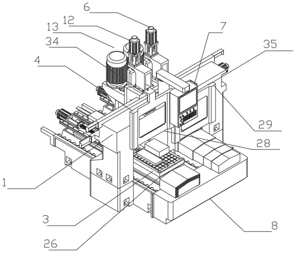
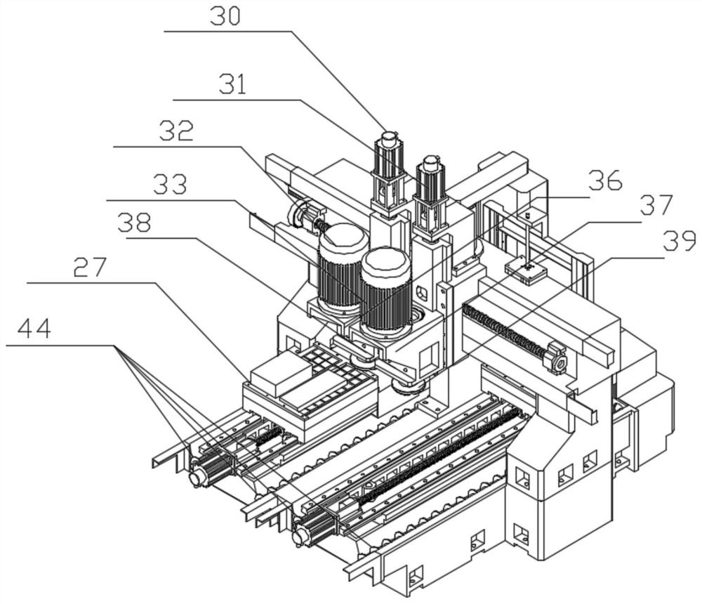
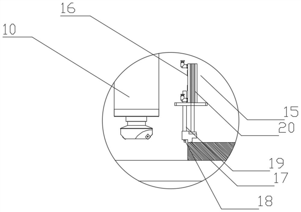
The invention discloses a metal steel plate end face chip milling device which comprises a door-shaped frame, a spindle motor, an electric control powerful magnetic disc, a movable lifting door, a lifting door regulation and control assembly, a lifting regulation and control assembly, a numerical control operation box, a working table, a fixing frame, a machine head and a cutter head. The door-shaped frame is arranged on the working table, and the lifting door regulation and control assembly is arranged on the door-shaped frame; the movable lifting door is arranged on the door-shaped frame, the movable lifting door is connected with the lifting door regulation and control assembly, the electric control powerful magnetic disc is arranged on the workbench, the fixing frame is arranged on the electric control powerful magnetic disc, the electric control powerful magnetic disc penetrates through the door-shaped frame, and the lifting regulation and control assembly is arranged on the door-shaped frame; and the numerical control operation box is arranged on the door-shaped frame, the spindle motor is arranged on the lifting regulation and control assembly, the machine head is arranged at the output shaft end of the spindle motor, and the cutter head is arranged on the machine head. The invention belongs to the technical field of intelligent mechanical equipment, and particularly relates to the metal steel plate end face chip milling device.

Description

technical field [0001] The invention belongs to the technical field of intelligent mechanical equipment, and specifically refers to a chip milling device for the end face of a metal steel plate. Background technique [0002] Steel processing needs to process six faces, and the upper and lower end faces are generally called planes. The plane processing area is the largest and the most difficult to process. The reason is that there is an oxide layer on it. In the past, ordinary gantry milling or powerful milling was used for processing. End milling, a powerful disk is installed on the machine tool. This kind of machine tool has a milling head with a cutter head. Rough milling and fine milling are also a cutter head. The up and down, forward, and left and right of the machine tool are manually operated. This manual machine tool has no CNC Driven by the setting value of the machine, the height of the steel must be uniform before it can be processed. If the plane height is differ...

Claims


Application Information

Patent Timeline
Patent Type & Authority Applications(China)
IPC IPC(8): B23C1/08B23C3/00B23Q3/06B23Q11/08B23Q17/20
CPCB23Q17/20B23C3/00B23C1/08B23Q11/08B23Q3/06
Inventor 潘炳汉
Owner 潘炳汉
Learn More