
Centering clamp for friction welding steel claw

A friction welding and centering fixture technology, which is applied in welding equipment, welding equipment, auxiliary welding equipment, etc., can solve problems affecting welding quality and efficiency, uneven distribution of clamping force, small clamping area, etc., to improve welding Uniform distribution of quality and clamping force, and the effect of reducing welding vibration

Pending Publication Date: 2021-10-08
兰州爱赛特机电科技有限公司 +1
View PDF0 Cites 1 Cited by
  • Summary
  • Abstract
  • Description
  • Claims
  • Application Information

AI Technical Summary

Problems solved by technology

[0003] At present, during the welding process of steel claws, due to the limitation of the fixture structure and the dimensional deviation of the outer surface of the steel claws, the clamping area is small, and the clamping force is unevenly distributed and weak, resulting in the welding process. Vibration in the medium, affecting welding quality and efficiency

Method used


Image

  • Centering clamp for friction welding steel claw

Examples


Embodiment Construction

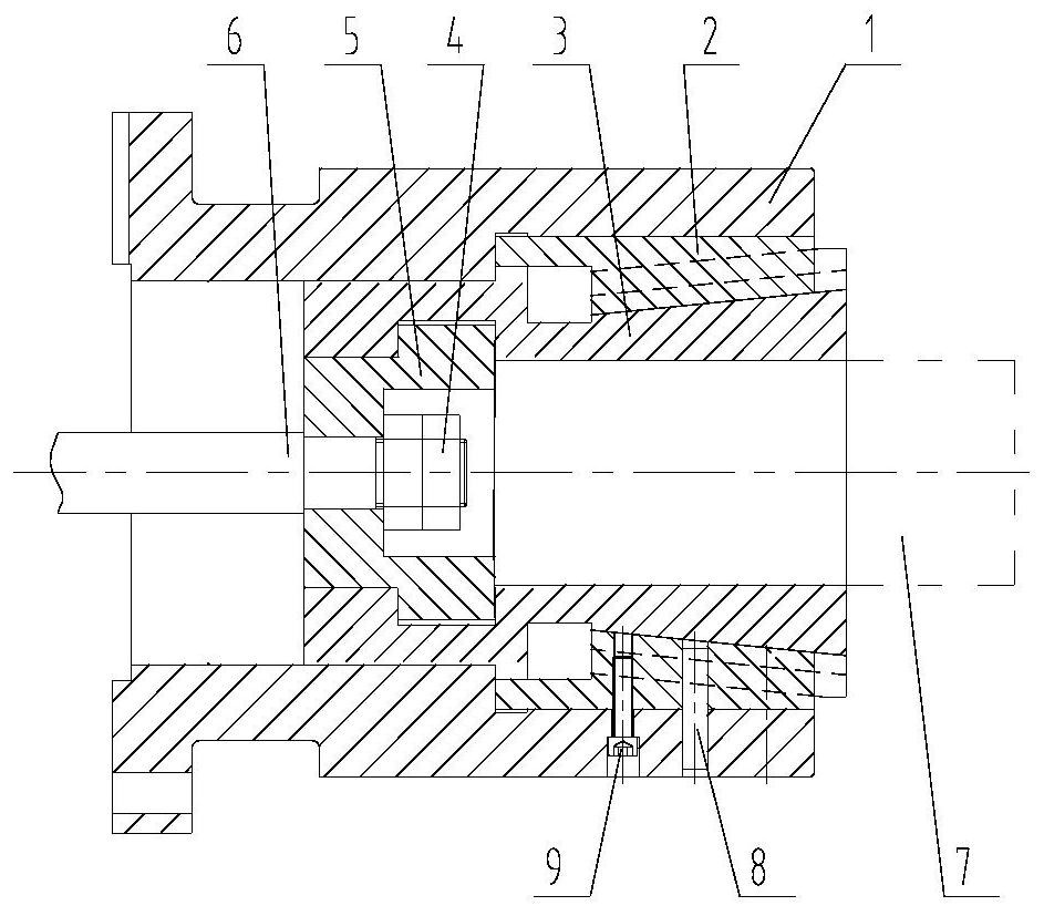
[0013] Such as figure 1 As shown, the centering fixture for friction welding steel claws includes: clamp body 1, steel claw sandwich core 3, pull rod 6, steel claw 7;

[0014] Before friction welding, the steel claw 7 is put into the inner hole of the clamp body 1, the right side wall of the steel claw sandwich core 3 has the same taper as the inner hole of the clamp body 1, and the inner surface formed by several steel claw sandwich cores 3 The surface of the hole is in contact with the outer circle of the steel claw 7, which plays the role of positioning and clamping at the same time when clamping; the left part of the steel claw sandwich 3 is connected to the pull rod 6, and the pull rod 6 is connected to the oil cylinder;

[0015] During welding, the steel claw sandwich core 3 moves to the left under the drive of the pull rod 6, and several steel claw sandwich cores 3 shrink and clamp the steel claws parallel to the center at the same time;

[0016] After the welding is c...


PUM


Abstract

The invention relates to a centering clamp for a friction welding steel claw. The centering clamp for the friction welding steel claw can enable clamping force to be evenly distributed, reduce welding vibration and improve clamping efficiency and welding efficiency, so that electrolytic aluminum welding quality is improved, welding time is shortened, and economic benefits of enterprises are improved. The clamp comprises a clamp body (1), steel claw cores (3), a pull rod (6) and a steel claw (7), before friction welding, the steel claw is placed in an inner hole of the clamp body, the right side walls of the steel claw cores and the inner hole of the clamp body have the same taper, the inner hole surface formed by the inner surfaces of the steel claw cores makes contact with the outer circle of the steel claw, and the effects of positioning and clamping are achieved during clamping; and the left part of each steel claw core is connected with the pull rod which is connected with an oil cylinder. In the welding process, the steel claw cores are driven by the pull rod to move leftwards, and the multiple steel claw cores move leftwards and contract towards the center in parallel to clamp the steel claw; and after welding is completed, the oil cylinder pushes the pull rod to enable the steel claw cores to move rightwards, and the steel claw is loosened.

Description

technical field [0001] The invention relates to the technical field of welding equipment, in particular to a centering fixture for friction welding steel claws, which is mainly used for positioning and clamping when the friction welding electrolysis guide rod steel claws are welded. Background technique [0002] The electrolytic anode in the electrolytic aluminum equipment is composed of carbon blocks, steel claws, and aluminum guide rods. The steel claws will be ablated or deformed during the electrolytic aluminum liquid process. After cutting off the steel claws, re-weld the new steel claws to the steel Claws on steel beams. [0003] At present, during the welding process of steel claws, due to the limitation of the fixture structure and the dimensional deviation of the outer surface of the steel claws, the clamping area is small, and the clamping force is unevenly distributed and weak, resulting in the welding process. The vibration in the machine will affect the welding...

Claims


Application Information

Patent Timeline
Patent Type & Authority Applications(China)
IPC IPC(8): B23K37/04B23K20/26B23K20/12
CPCB23K37/0435B23K20/26B23K20/122
Inventor 李鄂民芮执元沈浩靳岚赵俊天罗德春王鹏史新赵伟平辛舟王龙杨俊
Owner 兰州爱赛特机电科技有限公司
Learn More