Electromechanical equipment fault maintenance device
A technology for troubleshooting and electromechanical equipment, applied to workbenches, manufacturing tools, etc., can solve problems such as inconvenient use, inability to adapt clamping, etc., and achieve the effect of improving utilization
- Summary
- Abstract
- Description
- Claims
- Application Information
AI Technical Summary
Problems solved by technology
Method used
Image
Examples
Embodiment 1
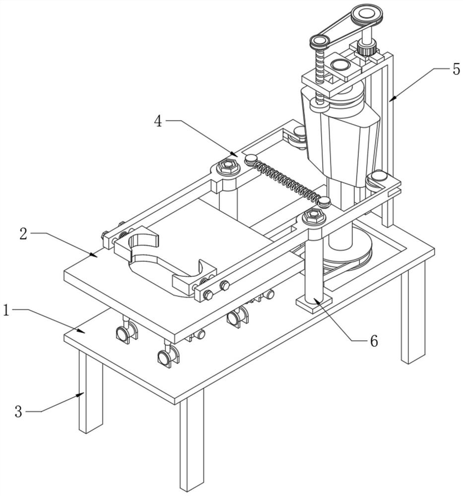
[0036] see Figure 1-4 , an electromechanical equipment troubleshooting device, comprising a mounting base 1 and a maintenance platform 2, the maintenance platform 2 is arranged above the mounting base 1, a clamping part 4 is arranged above the maintenance platform 2, and an adjustment assembly 5 is provided on the rear side of the clamping part 4 , a support rod 3 is fixedly connected to the lower corner of the mounting seat 1;
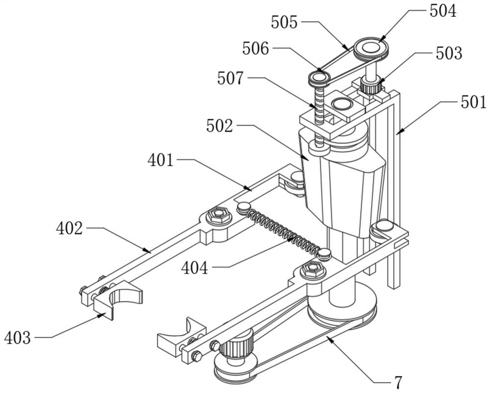
[0037] The clamping part 4 comprises a rear clamping bar 401 and a front clamping bar 402, and the rear clamping bar 401 is fixedly connected with the front clamping bar 402; Rotation is connected to the upper end of the fixed column 6, and the fixed column 6 is fixedly connected to the top of the mounting base 1;
[0038]A mounting piece is arranged on the upper side of the connection between the rear clamping rod 401 and the front clamping rod 402, and a tightening spring 404 is connected between the two mounting parts. A clamping block 403 is arr...
Embodiment 2
[0042] Such as Figure 4-6 , based on Example 1, the difference is that:
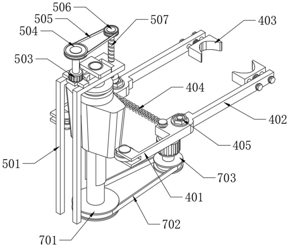
[0043] The adjustment assembly 5 includes a distance adjustment column 502, the lower end of the distance adjustment column 502 runs through the receiving groove 103, the center of the distance adjustment column 502 is provided with an engaging groove 512, and the inner side of the end of the rear clamping rod 401 is movably connected with a positioning wheel 406, and the positioning wheel 406 is connected to the distance adjustment The surface of the column 502 is in contact; a transmission shaft is arranged in the engagement groove 512, and engagement blocks 510 are fixedly connected to both sides of the transmission shaft, and the engagement blocks 510 are matched with the engagement groove 512; The lower end of the shaft is provided with a transmission assembly 7;
[0044] The connecting block 511 is fixedly connected to the upper side of the fixed frame 501, and the lower end of the fixed frame 50...
Embodiment 3
[0049] Such as Figure 7-10 , the lifting part A101 and the lifting part B102 have the same structure, the lifting part A101 includes a track frame 1011, and track grooves 1012 are opened on both sides of the track frame 1011, and a sliding column 1013 is slidably connected in the track groove 1012; the lower end of the sliding column 1013 is rotatably connected to a connecting rod 1014;
[0050] The lower end of the connecting rod 1014 is rotatably connected with a rotatable seat 1015, and the lower end of the rotatable seat 1015 is fixedly connected with the upper side of the mounting base 1; The other end is fixedly connected to the output shaft of the micromotor 1016, and the micromotor 1016 is fixedly connected to the outside of the track frame 1011;
[0051] In the present invention, by setting the lifting part A101 and the lifting part B102, when it is necessary to adjust the height of the maintenance platform 2 to adapt to the bottoming function of the electromechanic...
PUM
 Abstract
Description
Claims
Application Information
 - R&D
- Intellectual Property
- Life Sciences
- Materials
- Tech Scout
- Unparalleled Data Quality
- Higher Quality Content
- 60% Fewer Hallucinations
Browse by: Latest US Patents, China's latest patents, Technical Efficacy Thesaurus, Application Domain, Technology Topic, Popular Technical Reports.
© 2025 PatSnap. All rights reserved.Legal|Privacy policy|Modern Slavery Act Transparency Statement|Sitemap|About US| Contact US: help@patsnap.com


