Eureka AIR delivers breakthrough ideas for toughest innovation challenges, trusted by R&D personnel around the world.

Normal-temperature water catalysis hydrogen production method and equipment

A technology of hydrogen production equipment and room temperature water, applied in electrodes, cells, electrolysis process, etc., can solve the problem of not being able to be heated into water vapor, etc.

Active Publication Date: 2021-10-08
海慧特能源科技(广州)有限公司
View PDF7 Cites 1 Cited by
  • Summary
  • Abstract
  • Description
  • Claims
  • Application Information

AI Technical Summary

Problems solved by technology

[0003] The technical problem to be solved by the present invention is: how to make more full use of external heat sources for the production of hydrogen, even though these external heat sources cannot even heat water into water vapor

Method used


Image

  • Normal-temperature water catalysis hydrogen production method and equipment

Examples


Embodiment 1

[0041] The normal temperature water catalytic hydrogen production method of the present embodiment comprises the following steps:

[0042] 1) Continuously heat the pyroelectric catalyst, and the heating temperature is about 90°C;

[0043] 2) During the continuous heating process of the pyroelectric catalytic element, spray water at about 20°C from the top or side of the reactor on the pyroelectric catalytic element to cause different parts of the pyroelectric catalytic element to generate Temperature difference and thermal fluctuations, so that the water in contact with the pyroelectric catalytic element dissociates to generate H 2 ; After the sprayed water flows through the tourmaline powder in the pyroelectric catalyst, the temperature will increase, and when it reaches a certain temperature, such as 70°C, it will leave from the bottom of the reaction vessel or the water outlet on the other side.

[0044] 3) collect the H produced in step 2) 2 ;

[0045] 4) Collect the wa...

Embodiment 2

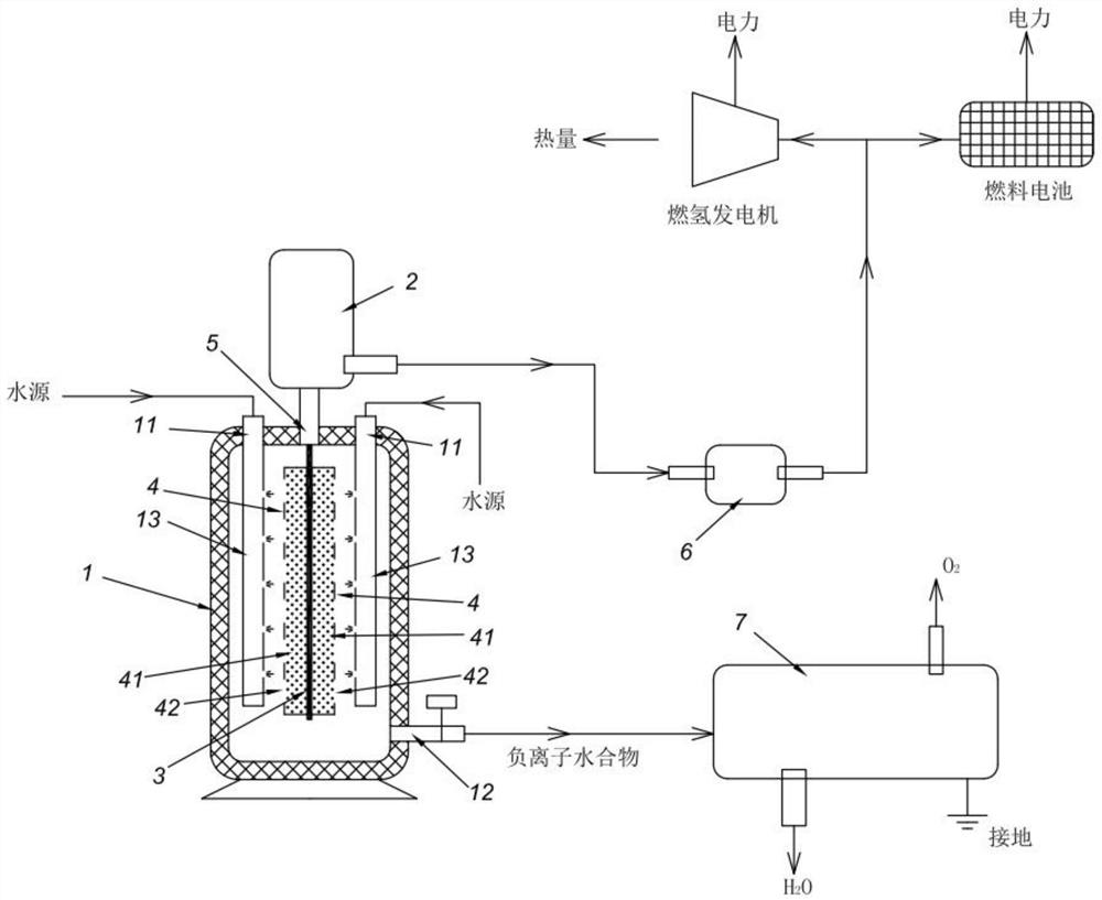
[0061] like figure 1 As shown, the room temperature water catalytic hydrogen production equipment in this implementation includes: a reaction vessel 1 , a condenser 2 , a heating component 3 and a pyroelectric catalytic component 4 . The heating element 3 wherein is an electric heating rod.

[0062] like figure 1 As shown, the reaction vessel 1 is provided with a water inlet 11 and a water outlet 12 . The water inlet 11 is arranged at the top of the reaction vessel 1 , and the water outlet 12 is arranged at the bottom of the reaction vessel 1 . The water inlet 11 communicates with the water nozzle 13 , and the water nozzle 13 finely and evenly sprays the water onto the pyroelectric catalytic element 4 . The heat-generating components 3 are distributed inside the reaction vessel 1 , and several pyroelectric catalytic elements 4 made into rods are installed around the outer circumference of the heat-generating components 3 . The pyroelectric catalytic element 4 of the presen...


PUM

PropertyMeasurementUnit
Energy consumptionaaaaaaaaaa

Abstract

The technical problem to be solved by the invention is how to fully utilize an external heat source to produce hydrogen. The normal-temperature water catalysis hydrogen production method comprises the steps of (1) continuously heating a pyroelectric catalysis piece at the heating temperature not exceeding the boiling temperature of water; (2) in the continuous heating process of the pyroelectric catalysis piece, spraying normal-temperature water to the pyroelectric catalysis piece so as to enable different parts on the pyroelectric catalysis piece to generate temperature difference and thermal fluctuation, and enabling water making contact with the pyroelectric catalysis piece to be dissociated to generate H2; and 3) collecting H2 generated in the step 2). The pyroelectric catalysis piece is a structure made of pyroelectric negative ion particles. According to the hydrogen production method, most of heat sources can be utilized for hydrogen production, and the hydrogen production method is an environment-friendly and low-cost energy scheme. The invention also provides hydrogen production equipment for implementing the hydrogen production method. The hydrogen production equipment has the advantages of simple and reliable structure, low manufacturing cost and hydrogen production cost, easiness in wide installation and use and the like.

Description

technical field [0001] The invention relates to a method for catalytic hydrogen production by normal temperature water and a hydrogen production equipment implementing the method. Background technique [0002] The Chinese invention patent 201210175876.0 entitled "Method and Equipment for Water Catalytic Hydrogen Production and Power Generation" discloses a hydrogen production method and equipment. The hydrogen production method and equipment need to heat water into water vapor, and allow a large amount of water vapor to enter the water decomposition container to react with negative ion powder in the water decomposition container to generate hydrogen. However, heating water into steam requires energy. Although it has been mentioned in the literature that industrial waste heat, solar energy and geothermal heat sources can be used to heat water into water vapor, if these external heat sources are not enough to heat water into water vapor, Then the hydrogen production efficienc...

Claims


Application Information

Patent Timeline
IPC IPC(8): C25B1/04C25B1/50C25B9/17C25B15/08C25B9/67C25B11/037C25B11/031C25B11/04
CPCC25B1/04C25B1/50C25B9/17C25B15/08C25B9/67C25B11/037C25B11/031C25B11/04Y02E60/36
Inventor 夏亚沈欧阳炎坤
Owner 海慧特能源科技(广州)有限公司
Why Eureka
Eureka Blog
Learn More