
Crisscross steel structural member spacing measuring equipment

A steel structure and criss-cross technology, which is applied in the field of cross-type steel structure spacing measurement equipment, can solve the problems of easy-to-wear measuring ends, contact of impurity particles, measurement errors, etc., to ensure accuracy, ensure stability, and avoid friction. Effect

Active Publication Date: 2021-10-08
南通诚利钢结构工程有限公司
View PDF5 Cites 0 Cited by
  • Summary
  • Abstract
  • Description
  • Claims
  • Application Information

AI Technical Summary

Problems solved by technology

[0004] However, during the use of the above-mentioned device, the measuring point cannot be effectively cleaned, so that the measuring end is easy to contact with the impurity particles at the measuring point, which is easy to wear the measuring end and cause measurement errors, and the measuring end is docked with the measuring point less stable

Method used


Image

  • Crisscross steel structural member spacing measuring equipment
  • Crisscross steel structural member spacing measuring equipment
  • Crisscross steel structural member spacing measuring equipment

Examples


Embodiment 1

[0027] The following examples are for illustrative purposes only and are not intended to limit the scope of the invention.

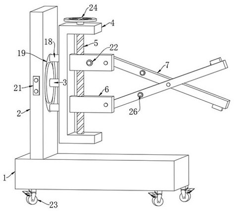
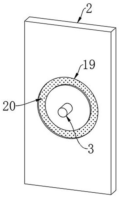
[0028] Such as Figure 1-5 As shown, a cross-type steel structure spacing measuring equipment includes a support base 1, a support plate 2 is fixedly connected to the support base 1, and a support shaft 3 is rotatably connected to the support plate 2, and the support shaft 3 is far away from the support plate 2. A frame 4 is fixedly connected to one end of the frame 4, and two metal blocks 18 are fixedly connected to the frame 4, and an annular chute 19 matching the two metal blocks 18 is provided on the support plate 2, and an electromagnetic chute 19 is embedded in the annular chute 19. strip 20, and the electromagnetic strip 20 is in contact with the metal block 18, and the support plate 2 is provided with a relay 21 electrically connected to the electromagnetic strip 20. Through the electromagnetic strip 20 provided, the magnetic change of the electr...

Embodiment 2

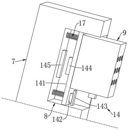
[0041] for Image 6 The second embodiment shown is different from the first embodiment in that a slider 27 is slidably connected to the protective groove 15, and the laser rangefinder 16 is arranged on the slider 27, and one side wall of the protective groove 15 is rotatably connected with a Nut cover 28, and screw rod 29 is threadedly connected in the nut cover 28, and one end of screw rod 29 extends to be set in the guard groove 15 and is fixedly connected with slide block 27, cooperates by the provided nut cover 28 and screw rod 29, makes later stage, can By turning the nut sleeve 28, the screw rod 29 pushes the laser rangefinder 16 to slide out of the protection groove 15, so that the user can disassemble and replace it conveniently.


PUM


Abstract

The invention belongs to the technical field of steel structural member spacing measurement, and relates to crisscross steel structural member spacing measurement equipment. The equipment comprises a supporting seat, a supporting plate is fixedly connected to the supporting seat, a supporting shaft is rotatably connected to the supporting plate, a frame is fixedly connected to the end, away from the supporting plate, of the supporting shaft, the frame is rotationally connected with a bidirectional lead screw, the bidirectional lead screw is in threaded connection with two supporting blocks, and the two supporting blocks are both in sliding connection with the frame. In the measuring process, impurity particles attached to the position near a measuring point can be cleaned in time; after a positioning base is in butt joint with the measuring point, under the action of a direction-changing switch mechanism, a driving mechanism automatically changes a transmission direction, so that all the direction-changing fans can conduct air suction operation; on the basis of negative pressure principle, each air hole tightly sucks a measuring point, and the stability of the measuring process is ensured.

Description

technical field [0001] The invention belongs to the technical field of distance measurement of steel structural parts, and in particular relates to a cross-type distance measurement device for steel structural parts. Background technique [0002] Steel structure is a type of building commonly used in construction. The overall structure is mainly composed of steel beams, steel columns, steel trusses and other components made of section steel and steel plates. During the manufacturing and overall closing process, it is necessary to measure the distance between the two reinforcement members to verify the segmental manufacturing accuracy and the closing positioning accuracy. [0003] The existing patent (Application No.: CN202021968903.6) is a cross-type steel structure spacing measuring device. The cross-type steel structure spacing measuring device includes a suspension measuring arm, a base point measuring arm and a ruler; there is a rotation center point between the suspens...

Claims


Application Information

Patent Timeline
IPC IPC(8): G01B11/14B08B5/02
CPCG01B11/14B08B5/02
Inventor 施海涛
Owner 南通诚利钢结构工程有限公司
Features
  • Generate Ideas
  • Intellectual Property
  • Life Sciences
  • Materials
  • Tech Scout
  • Unparalleled Data Quality
  • Higher Quality Content
  • 60% Fewer Hallucinations
Learn More