Unmanned vehicle position detection method and device, equipment, storage medium and vehicle
A detection method, unmanned vehicle technology, applied in vehicle position/route/height control, motor vehicles, transportation and packaging, etc., can solve the problems of low accuracy, reduce the accuracy of 3D position coordinates of obstacles, and achieve improved The effect of accuracy
- Summary
- Abstract
- Description
- Claims
- Application Information
AI Technical Summary
Problems solved by technology
Method used
Image

Examples
Embodiment 1
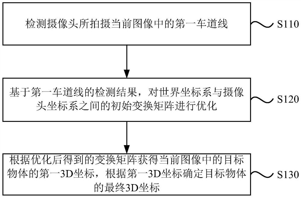
[0031] figure 1 It is a flowchart of an unmanned vehicle position detection method provided in Embodiment 1 of the present invention. This embodiment can be applied to the situation of detecting the 3D coordinate position of a target object in an unmanned vehicle system. This method can be detected by an unmanned vehicle position This device can be composed of hardware and / or software, and can generally be integrated into a device with the function of detecting the position of an unmanned vehicle. This device can be an electronic device such as a mobile terminal or a vehicle-mounted device. Such as figure 1 As shown, the method specifically includes the following steps:
[0032] S110. Detect the first lane line in the current image captured by the camera.
[0033] Specifically, during the driving process of the unmanned vehicle, the on-board camera continuously acquires the image in front of the vehicle. When the camera captures the current image, it detects the first lane l...
Embodiment 2
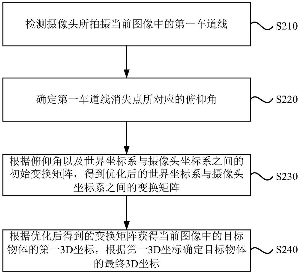
[0056] figure 2 It is a flow chart of an unmanned vehicle position detection method provided in Embodiment 2 of the present invention. Based on the above implementation, based on the detection result of the first lane line, the initial transformation matrix between the world coordinate system and the camera coordinate system is performed. Optimization can be implemented in the following way: determine the pitch angle corresponding to the vanishing point of the first lane line, the pitch angle refers to the angle between the optical axis of the camera and the ground plane; according to the pitch angle and the world coordinate system and the camera coordinate system The initial transformation matrix between is obtained, and the transformation matrix between the optimized world coordinate system and the camera coordinate system is obtained. Such as figure 2 As shown, the method specifically includes the following steps:
[0057] S210. Detect the first lane line in the current...
Embodiment 3
[0077] Figure 4 It is a schematic structural diagram of an unmanned vehicle position detection device provided in Embodiment 3 of the present invention. Such as Figure 4 As shown, the device includes: a first lane line detection module 410 , a pitch angle determination module 420 , a pitch angle smoothing and denoising module 430 , an initial transformation matrix optimization module 440 and a 3D coordinate determination module 450 .
[0078] The first lane line detection module 410 is configured to detect the first lane line in the current image captured by the camera;
[0079] The pitch angle determination module 420 is configured to determine the pitch angle corresponding to the vanishing point of the first lane line, and the pitch angle refers to the angle between the optical axis of the camera and the ground plane;
[0080] The pitch angle smoothing and denoising module 430 is configured to, according to the pitch angle corresponding to the vanishing point of the lane...
PUM
 Abstract
Description
Claims
Application Information
 - Generate Ideas
- Intellectual Property
- Life Sciences
- Materials
- Tech Scout
- Unparalleled Data Quality
- Higher Quality Content
- 60% Fewer Hallucinations
Browse by: Latest US Patents, China's latest patents, Technical Efficacy Thesaurus, Application Domain, Technology Topic, Popular Technical Reports.
© 2025 PatSnap. All rights reserved.Legal|Privacy policy|Modern Slavery Act Transparency Statement|Sitemap|About US| Contact US: help@patsnap.com