Product surface milling device

A milling device and product technology, applied in the direction of positioning device, feeding device, milling machine equipment, etc., can solve the problems of different thickness of black leather, poor universality of fixtures, unfavorable metal reprocessing, etc., to avoid misoperation of workers, realize protection work, The effect of saving manpower

Pending Publication Date: 2021-10-12
SOHBI CRAFT CHANGSHU
View PDF0 Cites 0 Cited by
  • Summary
  • Abstract
  • Description
  • Claims
  • Application Information

AI Technical Summary

Problems solved by technology

[0002] At present, during the production process of some metals, due to the tempering process, a layer of black skin will be formed on the surface, resulting in a rough surface of the product, which is not conducive to the reprocessing of the metal. Therefore, it is necessary to carry out secondary processing. Remove the black skin on the metal surface
However, due to the special shape of the product, it is impossible to use a general-purpose tool to mill the black skin: because the material of the product is different, the tempering time is also different, so the thickness of the black skin is also different, resulting in a different milling thickness.
Traditional milling equipment can only mill one thickness, and its universal performance is poor. When the milling product changes or the milling thickness changes, it is necessary to perform tool calibration on the cutterhead, and the equipment stops for a long time; the product fixture has poor versatility. When replacing the product, the corresponding fixture also needs to be changed

Method used


Image

  • Product surface milling device
  • Product surface milling device
  • Product surface milling device

Examples


Embodiment Construction

[0032] In order to make it easier for those skilled in the art to understand the present invention, the specific implementation manners of the present invention will be described below with reference to the accompanying drawings.

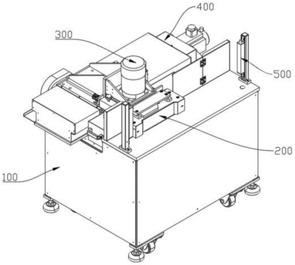
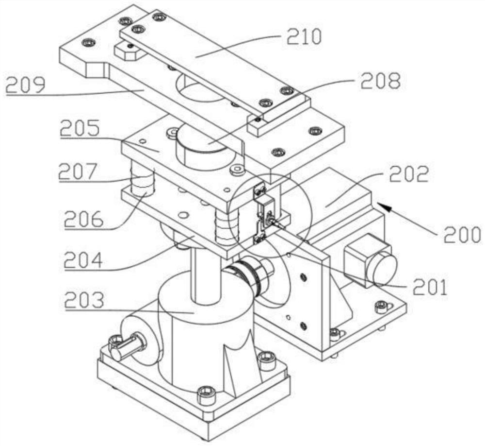
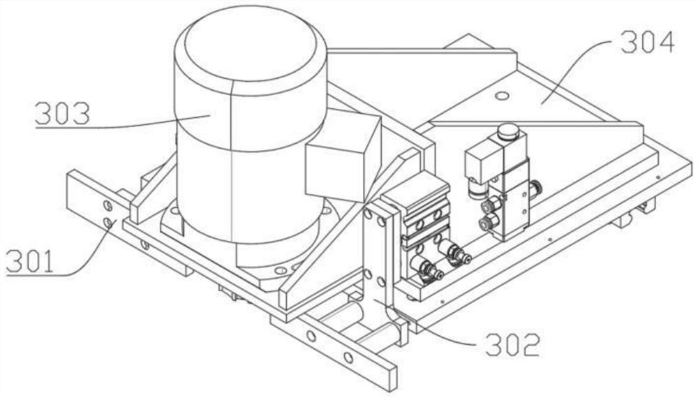
[0033] like Figure 1 to Figure 8 As shown, the present invention provides a product surface milling device, including a frame 100, a product lifting module 200, a cutter head module 300 and a cutter head moving module 400, and the upper side of the frame 100 is provided with the product Lifting module 200, one side of the product lifting module 200 is provided with the cutter head module 300, the cutter head module 300 is fixed on the cutter head moving module 400, and the cutter head moving module 400 is fixed on the upper surface of the frame 100 . By setting the frame 100, the product price increase module, the cutter head module 300 and the cutter head moving module 400 can be installed on the frame 100 to form the whole black leather milling ...


PUM


Abstract

The invention relates to the field of product machining, in particular to a product surface milling device. The product surface milling device comprises a rack, a product lifting module, a tool bit module and a tool bit moving module; the product lifting module is arranged on the upper side of the rack; the tool bit module is arranged on one side of the product lifting module and fixed to the tool bit moving module; the tool bit moving module is fixed to the upper surface of the rack; the product lifting module comprises a lifting sensing module, a lifting motor, a lead screw lifting machine, a lower pressing plate, an upper pressing plate, a guide column, a spring, a top column, a first base plate and a second base plate; the lifting motor is connected with the lead screw lifting machine; and the lead screw lifting machine is connected with the lower pressing plate. According to the product surface milling device, the black skin removing work of a to-be-milled product is realized, the application range of a cutter is wide, the adjusting speed is high, and the requirements on different milling thicknesses are met.

Description

technical field [0001] The invention relates to the field of product processing, in particular to a product surface milling device. Background technique [0002] At present, during the production process of some metals, due to the tempering process, a layer of black skin will be formed on the surface, resulting in a rough surface of the product, which is not conducive to the reprocessing of the metal. Therefore, it is necessary to carry out secondary processing. Remove black scale from metal surfaces. However, due to the special shape of the product, it is impossible to use a general-purpose tool to mill the black skin: because the material of the product is different, the tempering time is also different, so the thickness of the black skin is also different, resulting in a different milling thickness. . Traditional milling equipment can only mill one thickness, and its universal performance is poor. When the milling product changes or the milling thickness changes, it is ...

Claims


Application Information

Patent Timeline
Patent Type & Authority Applications(China)
IPC IPC(8): B23C3/14B23C9/00B23Q1/25B23Q3/06B23Q5/40B23Q7/06B23Q11/00B23Q17/24
CPCB23C3/14B23C9/00B23Q3/06B23Q1/25B23Q5/40B23Q11/0082B23Q17/24B23Q7/06
Inventor 尹佳玮谢利峰高健潘虎
Owner SOHBI CRAFT CHANGSHU
Why Eureka
Try Eureka