
Combined positioning system, method, device and medium for rpa positioning control elements

A combination of positioning and element technology, applied in the direction of program control devices, user interface execution, etc., can solve problems such as low positioning efficiency and accuracy, target control positioning, and large limitations of RPA locators, so as to improve positioning accuracy and improve The effect of positioning efficiency and increasing general adaptability

Active Publication Date: 2021-12-03
CHANGSHA BIOVISION SOFTWARE TECH CO LTD
View PDF9 Cites 0 Cited by
  • Summary
  • Abstract
  • Description
  • Claims
  • Application Information

AI Technical Summary

Problems solved by technology

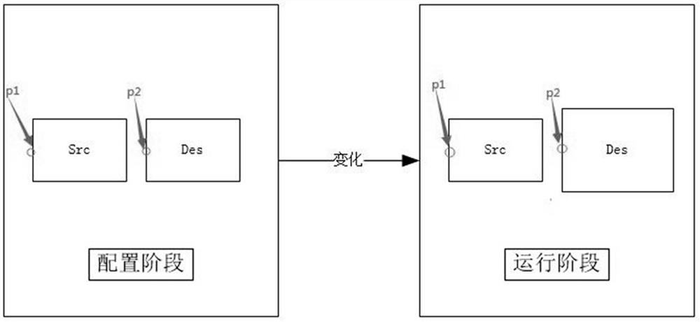
However, when the interface of the target software changes, the following situations are likely to occur: 1) Path locator: When the target software window hierarchy changes due to the update of the display content, the level of the target control in the form structure is different from that configured by the designer. The target control cannot be positioned due to inconsistent path levels; 2) Position locator: When the size and position of the target control change slightly, the position of the control relative to the software form interface is inconsistent with the relative position configured in the designer stage, so it cannot be positioned. Position the target control; 3) Image locator: When the display effect (color, size, text) of the control changes, the screenshot of the control is inconsistent with the screenshot of the control in the designer, and the target control cannot be positioned
[0005] According to the relevant scheme, the current RPA locator has great limitations, and usually cannot achieve accurate positioning effect when the target software interface changes
Moreover, the RPA locator at this stage usually realizes the positioning function alone, and the positioning efficiency and accuracy are low.

Method used


Image

  • Combined positioning system, method, device and medium for rpa positioning control elements
  • Combined positioning system, method, device and medium for rpa positioning control elements
  • Combined positioning system, method, device and medium for rpa positioning control elements

Examples


Embodiment Construction

[0032] Embodiments of the present invention are described in detail below, examples of which are shown in the drawings, wherein the same or similar reference numerals designate the same or similar elements or elements having the same or similar functions throughout. The embodiments described below by referring to the figures are exemplary only for explaining the present invention and should not be construed as limiting the present invention.

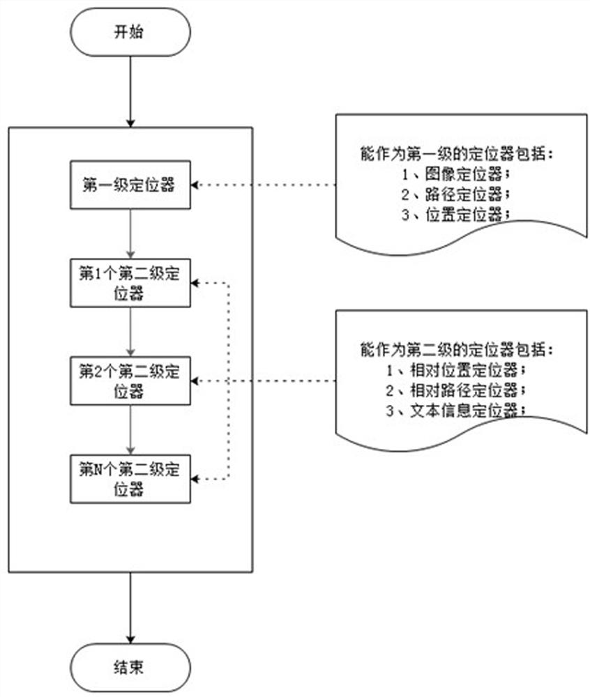
[0033] Before introducing the embodiments of the present invention, first introduce the relevant technical solutions of the present invention: the RPA locator at the present stage mainly includes a path locator, a position locator and an image locator; among them,

[0034] 1) Path locator: In the configuration phase, the control to be operated is used as positioning information relative to the target software interface hierarchy where it is located, and in the running phase, the corresponding control is searched from the target window str...


PUM


Abstract

The invention discloses a combined positioning system, method, device and medium for RPA positioning control elements. This solution combines a first-level locator with at least one second-level locator to adapt to the flexible and changeable situation of the target software The function of accurately locating the target element is still possible, and the universal adaptability of the locator positioning function is increased. The positioning accuracy and positioning efficiency can be improved through flexible combination methods. Moreover, the second-level locator in the present invention is based on the relatively unchanged features between the selected reference control element and the target control element to be positioned, and then based on the positioned reference control element and the relatively unchanged features to be positioned Compared with related solutions, when the target software interface changes, it can still achieve accurate positioning effect.

Description

technical field [0001] The invention relates to the technical field of RPA software process automatic robot, in particular to a combined positioning system, method, device and medium for RPA positioning control elements. Background technique [0002] RPA (Robotic Process Automation) is a new type of artificial intelligence virtual process automation robot that can replace or assist humans to complete repetitive tasks in digital devices such as computers and mobile phones. VBA (Visual Basic for Applications, macro language) is a macro language based on Microsoft's software development platform Visual Basic. It is a type of programming language that performs general automation (OLE) tasks in Windows desktop applications. VBA is a typical macro programming language application. A macro (Macro in English) is composed of some independent commands. When an interpreter or compiler encounters a macro language, it will parse and convert these small commands or actions into a series ...

Claims


Application Information

Patent Timeline
Patent Type & Authority Patents(China)
IPC IPC(8): G06F9/451
CPCG06F9/451
Inventor 梁威匡雄峰
Owner CHANGSHA BIOVISION SOFTWARE TECH CO LTD
Learn More