Electronic device

A technology for electronic equipment and keycaps, applied in electrical equipment shells/cabinets/drawers, circuits, electrical switches, etc., can solve the problems of difficult assembly, limited installation space, and reduced structural performance of the end of the snap ring and the key post, etc. To achieve the effect of reducing assembly difficulty, improving stability and ensuring stability

Pending Publication Date: 2021-10-12
GUANGDONG OPPO MOBILE TELECOMM CORP LTD
View PDF0 Cites 4 Cited by
  • Summary
  • Abstract
  • Description
  • Claims
  • Application Information

AI Technical Summary

Problems solved by technology

Due to the limited installation space at the end of the key column, the structural performance of the snap ring and the end of the key column is reduced, and there is difficulty in assembly

Method used


Image

  • Electronic device
  • Electronic device
  • Electronic device

Examples


Embodiment Construction

[0024] The following will clearly and completely describe the technical solutions in the embodiments of the application with reference to the drawings in the embodiments of the application.

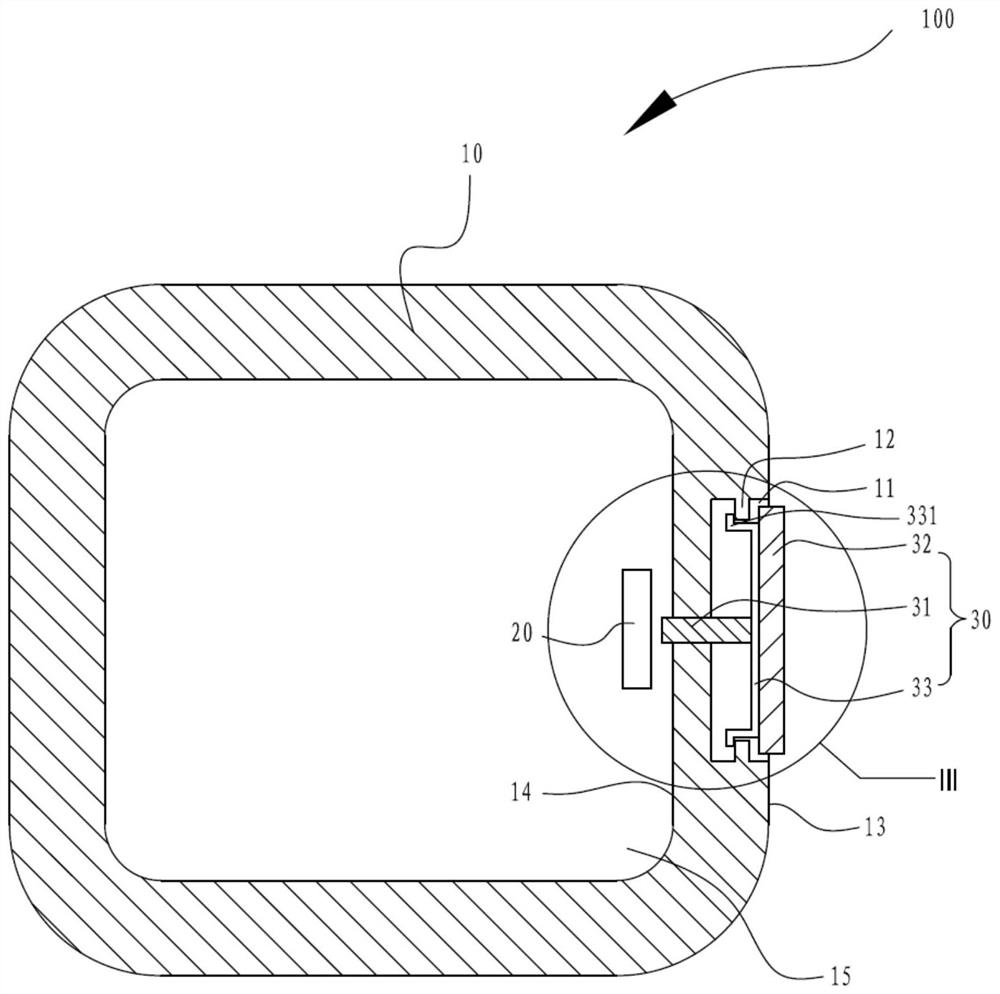
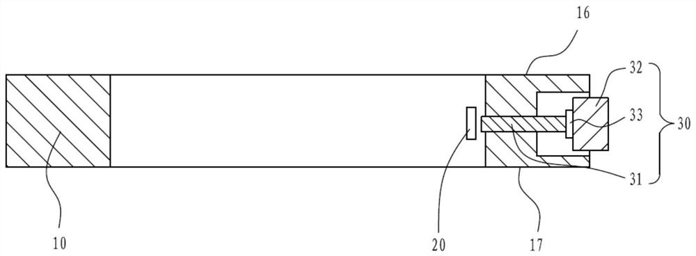
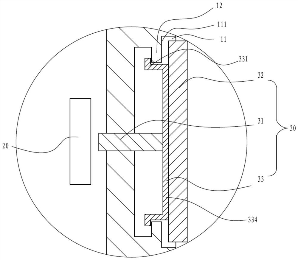
[0025] see figure 1 , figure 2 and image 3 , the present application provides an electronic device 100, the electronic device 100 includes a frame 10, a signal trigger device 20 fixed inside the frame 10 and a button 30 mounted on the frame 10, the frame 10 is provided with The button hole 11 facing the signal trigger device 20 is provided with a stop protrusion 12 on the inner wall of the button hole 11 , and the button 30 includes a key column passing through the frame 10 and adjacent to the signal trigger device 20 31. The key cap 32 connected to the key column 31 and matched with the key hole 11, and the clamp plate 33 buckled on the side of the key cap 32 facing the signal trigger device 20, the clamp plate 33 is provided with The hook 331 is limitedly matched with the stop prot...


PUM


Abstract

The invention discloses an electronic device which comprises a frame, a signal trigger device fixed on the inner side of the frame and a key installed on the frame in a penetrating mode, the frame is provided with a key hole right opposite to the signal trigger device, and the inner side wall of the key hole is provided with a stop protrusion. The key comprises a key column, a key cap and a clamping plate, wherein the key column penetrates through the frame and is adjacent to the signal trigger device, the key cap is connected with the key column and is matched with the key hole, the clamping plate is buckled to the side, facing the signal trigger device, of the key cap, and the clamping plate is provided with a clamping hook matched with the stopping protrusion in a limiting mode. According to the key structure, the clamping hooks of the clamping plate realize safe limiting and separation prevention of the key cap, and the stability of the clamping plate and the key cap is ensured, so that the stability of the key structure is improved, and the assembly difficulty is reduced.

Description

technical field [0001] The application relates to the field of communication equipment, especially an electronic equipment. Background technique [0002] At present, buttons are provided in all electronic devices, so as to use the buttons to control the electronic devices. At present, the key is often provided with a snap ring at the end of the key column, and the snap ring is held against the limit structure, and the limit structure is used to limit the snap ring, so as to prevent the key from breaking away from the frame of the electronic device and ensure the safety of the key. Due to the limited installation space at the end of the key column, the structural performance of the snap ring and the end of the key column is reduced, and there is difficulty in assembling. Contents of the invention [0003] An embodiment of the present application provides an electronic device, wherein the electronic device includes a frame, a signal trigger device fixed inside the frame, an...

Claims


Application Information

Patent Timeline
Patent Type & Authority Applications(China)
IPC IPC(8): H01H13/14H01H13/04H05K5/02
CPCH01H13/14H01H13/04H05K5/0217
Inventor 范伟
Owner GUANGDONG OPPO MOBILE TELECOMM CORP LTD
Why Eureka
Try Eureka