Supercharge Your Innovation With Domain-Expert AI Agents!

Rotor punching sheet, rotor of motor, motor and vehicle

A technology of rotor punching and air gap, which is applied in the field of vehicles, can solve problems such as failure of magnetic isolation bridge fracture, magnetic flux leakage, and poor magnetic performance, and achieve the effects of increasing service life, improving magnetic performance, and reducing stress

Active Publication Date: 2021-10-12
安庆威灵汽车部件有限公司 +2
View PDF8 Cites 0 Cited by
  • Summary
  • Abstract
  • Description
  • Claims
  • Application Information

AI Technical Summary

Problems solved by technology

[0002] In the related art, the rotor is provided with permanent magnet installation grooves for installing permanent magnets. The structure of the permanent magnet installation grooves leads to stress concentration, which leads to easy fracture of the rotor punches, such as the failure of the magnetic isolation bridge. Therefore, in order to ensure the mechanical strength The width of the magnetic isolation bridge is often designed to be large, resulting in serious magnetic flux leakage, and it is often necessary to select a silicon steel sheet with high strength and poor magnetic properties for processing the rotor sheet

Method used


Image

  • Rotor punching sheet, rotor of motor, motor and vehicle
  • Rotor punching sheet, rotor of motor, motor and vehicle
  • Rotor punching sheet, rotor of motor, motor and vehicle

Examples


Embodiment Construction

[0038] Embodiments of the present invention are described in detail below, examples of which are shown in the drawings, wherein the same or similar reference numerals designate the same or similar elements or elements having the same or similar functions throughout. The embodiments described below by referring to the figures are exemplary only for explaining the present invention and should not be construed as limiting the present invention.

[0039] In describing the present invention, it should be understood that the terms "center", "longitudinal", "transverse", "length", "width", "thickness", "upper", "lower", "front", " Back", "Left", "Right", "Vertical", "Horizontal", "Top", "Bottom", "Inner", "Outer", "Clockwise", "Counterclockwise", "Axial" , "radial", "circumferential" and other indicated orientations or positional relationships are based on the orientations or positional relationships shown in the drawings, which are only for the convenience of describing the present ...


PUM


Abstract

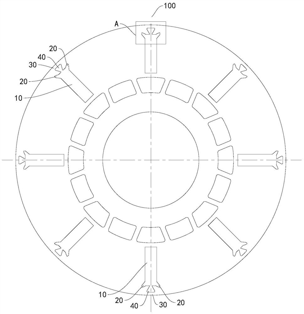
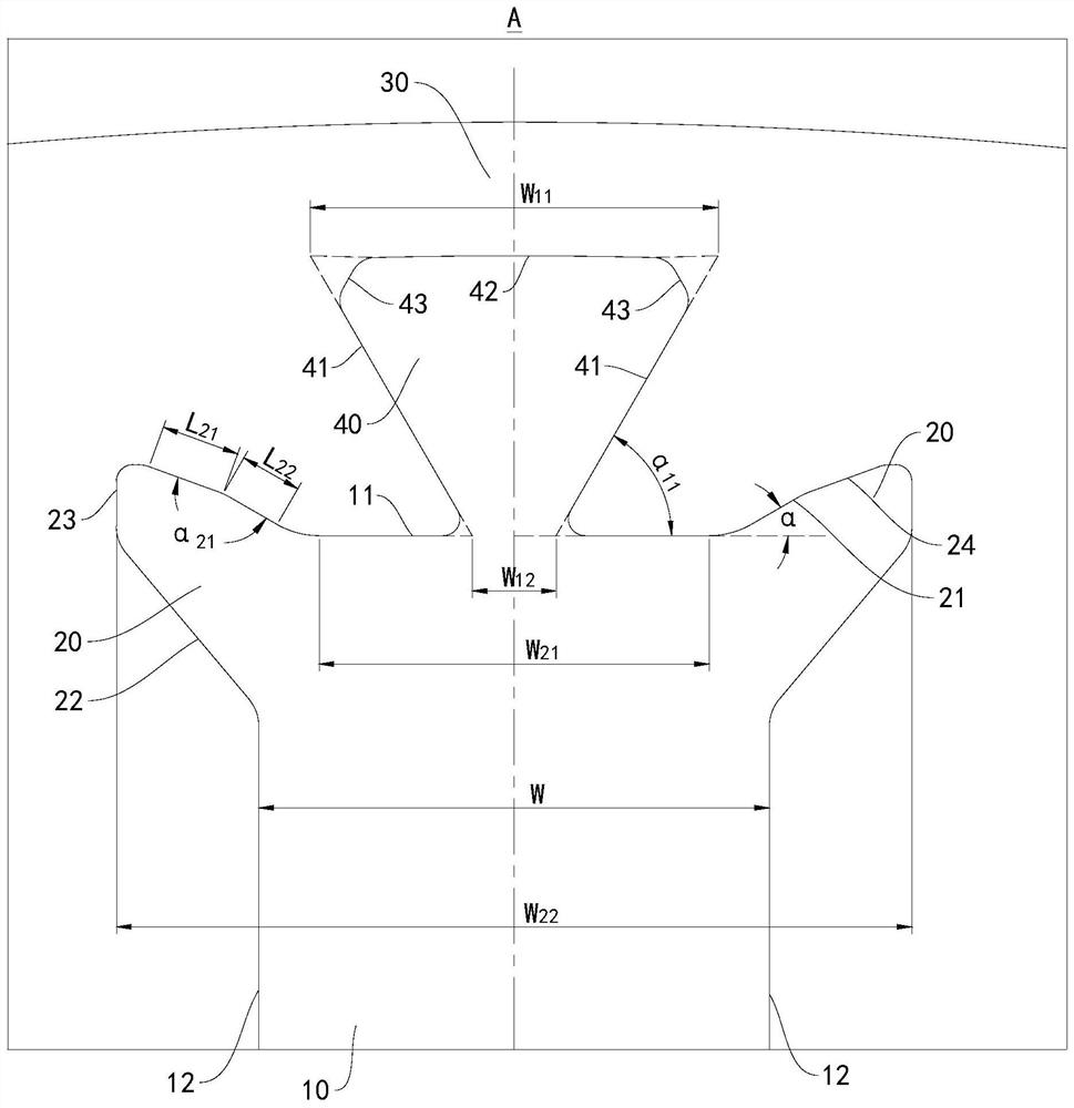
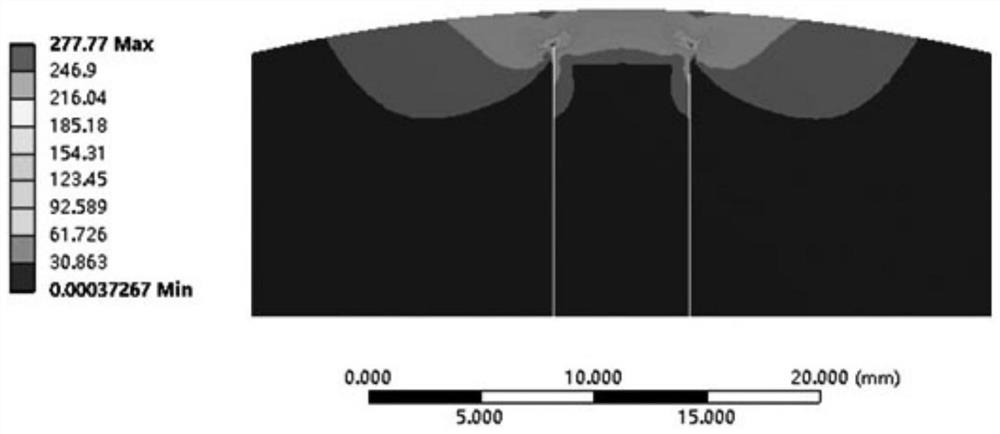
The invention discloses a rotor punching sheet, a motor rotor, a motor and a vehicle, the rotor punching sheet is provided with a plurality of groove groups, each groove group comprises a permanent magnet mounting groove and two first air gap grooves, in the circumferential direction of the rotor punching sheet, the two first air gap grooves are respectively arranged at two sides of the permanent magnet mounting groove and are communicated with the permanent magnet mounting groove, The groove group is provided with a base line which extends in the radial direction of the rotor punching sheet and passes through the midpoint of the outer groove wall of the permanent magnet mounting groove, the first air gap groove is provided with a first side groove wall connected with the outer groove wall of the permanent magnet mounting groove, the first side groove wall obliquely extends outwards in the direction far away from the base line, and the included angle between the vertical line of the base line and the first side groove wall is [alpha], 0 degree<[alpha]<=75 degrees. According to the embodiment of the invention, the maximum stress point of the rotor punching sheet deviates, and the maximum stress value is remarkably reduced, so that the stress at the outer groove wall of the permanent magnet mounting groove is remarkably reduced, the rotor punching sheet is not easy to break, and a silicon steel sheet with better magnetic performance can be selected while the mechanical strength requirement is met.

Description

technical field [0001] The invention relates to the technical field of vehicles, and more specifically, to a rotor punch, a rotor of a motor, a motor and a vehicle. Background technique [0002] In the related art, the rotor is provided with permanent magnet installation grooves for installing permanent magnets. The structure of the permanent magnet installation grooves leads to stress concentration, which leads to the easy fracture of the rotor punches, such as the failure of the magnetic isolation bridge. Therefore, in order to ensure the mechanical strength The width of the magnetic isolation bridge is often designed to be large, resulting in serious magnetic flux leakage, and it is often necessary to select silicon steel sheets with high strength and poor magnetic properties for processing rotor laminations. Contents of the invention [0003] The present invention aims to solve at least one of the technical problems existing in the prior art. For this reason, an objec...

Claims


Application Information

Patent Timeline
Patent Type & Authority Applications(China)
IPC IPC(8): H02K1/27H02K21/02
CPCH02K1/2766H02K1/2786H02K21/028H02K2213/03
Inventor 陈佳慧
Owner 安庆威灵汽车部件有限公司
Features
  • R&D
  • Intellectual Property
  • Life Sciences
  • Materials
  • Tech Scout
  • Unparalleled Data Quality
  • Higher Quality Content
  • 60% Fewer Hallucinations
Learn More