Anti-crease non-winding type trimming machine

A coiling and shearing machine technology, which is applied in textiles and papermaking, knitting, warp knitting, etc., can solve the problems that the fabric cannot be cut neatly, the gray cloth or floating thread is not cut cleanly, and the tension of the shearing machine is not enough. Sustainable production, high practical value, and guaranteed tidy effect

Pending Publication Date: 2021-10-15
MAANSHAN HAINA ELECTRONICS TECH
View PDF7 Cites 1 Cited by
  • Summary
  • Abstract
  • Description
  • Claims
  • Application Information

AI Technical Summary

Problems solved by technology

However, in the prior art, shearing machines are divided into non-coiling type and coiling type, and the cloth receiving method is non-coiling type, which will cause new problems, that is, the tension required by the shearing machine is not enough, and the gray cloth is on the shearing machine. Insufficient tension when trimming the thread can easily cut the gray fabric or the floating thread cannot be cut cleanly. The tensile strength of warp-knitted gray fabric production and shearing is revealed. At the same time, due to the softness of the warp-knitted fabric, cutting cannot guarantee the neatness of the fabric.

Method used


Image

  • Anti-crease non-winding type trimming machine
  • Anti-crease non-winding type trimming machine
  • Anti-crease non-winding type trimming machine

Examples


Embodiment 1

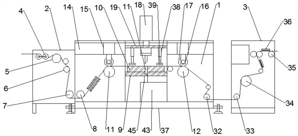
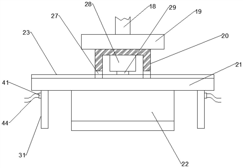
[0025] Such as Figure 1-4 As shown, the shearing machine according to the embodiment of the present invention includes a shearing box 1, an expanding box 2 and a connecting box 3, and the shearing box 1 is located between the expanding box 2 and the connecting box 3. The middle part of the connection box 3, the expansion box 2 and the connection box 3 are located at the two ends of the shear box 1, the inside of the expansion box 2 is provided with a tension angle roller 4, and the tension angle roller 4 One side of the expansion roller 5 is provided with a centering structure 6 at the lower end of the expansion roller 5, and a traction roller-7 is provided at the lower end of the centering structure 6, and the inner side of the shearing box 1 is provided with Traction roller 2 8 is arranged, and the interior middle part of described shearing box 1 is provided with fixed plate 9, and the upper end middle part of described fixed plate 9 is provided with shearing table 10, and ...

Embodiment 2

[0028] Such as Figure 1-4As shown, the lower ends of the shear box 1, the expansion box 2 and the connection box 3 are provided with a support plate 37, and the lower end of the shear box 1 and both sides of the support plate 37 are provided with The connecting bottom plate is provided with adjustable feet at both ends of the connecting bottom plate. The centering structure 6 is composed of two rudder rollers and a centering infrared sensor.

[0029] Such as Figure 1-4 As shown, sliders are provided on both sides of the lifting plate 19 , and slide grooves matching the sliders are provided on both sides of the shear box 1 located at the connecting frame 14 . The lower end of the lifting plate 19 and the both sides of the transverse blade 22 are provided with a spring telescopic rod 38, the lower end of the spring telescopic rod 38 is provided with a pressing plate 39, and the bottom end of the pressing plate 39 is provided with an anti-skid Rubber mat. Both sides of the ...


PUM


Abstract

The invention discloses an anti-crease non-winding type trimming machine. The machine comprises a trimming box, an expanding box and a connecting box; the trimming box is located between the expanding box and the connecting box; the expanding box and the connecting box are located at the two ends of the trimming box; a tension angle roller is arranged in the expanding box; an expanding roller is arranged on one side of the tension angle roller; a centering structure is arranged at the lower end of the spreading roller; a first traction roller is arranged at the lower end of the centering structure; a second traction roller is arranged on one side of the interior of the trimming box; a fixing plate is arranged in the middle of the interior of the trimming box; a trimming table is arranged in the middle of the upper end of the fixing plate; a cloth guide roller is arranged on one side of the lower end of the interior of the connecting box; a cloth collecting traction roller is arranged in the middle of the interior of the connecting box; a cloth guide bar is arranged at one end of the cloth collecting traction roller; and a plurality of static elimination plates are arranged on the side edge, located on the cloth collecting traction roller, of the connecting box. The machine has the beneficial effects that sustainable production of a production line is guaranteed, meanwhile, the qualified rate of products is guaranteed, and the machine has the advantages of being rapid, time-saving and labor-saving.

Description

technical field [0001] The invention relates to the technical field of textile machinery, in particular to an anti-crease non-coiling thread cutting machine. Background technique [0002] Using one or several groups of yarns arranged in parallel to form knitted fabrics on all the working needles of the warp feeding machine at the same time, this method is called warp knitting, and the fabric is called warp knitted fabric. The pattern characteristics of warp-knitted fabrics are formed by the mutual cooperation of the ground net weave and the floral yarn weave, that is to say, the difference between the patterns of warp-knitted fabrics is mainly determined by the difference in the ground net weave or the floral yarn weave. However, in the prior art, shearing machines are divided into non-coiling type and coiling type, and the cloth receiving method is non-coiling type, which will cause new problems, that is, the tension required by the shearing machine is not enough, and the g...

Claims


Application Information

Patent Timeline
Patent Type & Authority Applications(China)
IPC IPC(8): D04B35/34D04B35/32D04B27/34
CPCD04B35/34D04B35/32D04B27/34
Inventor 丁鑫龙吴金桃
Owner MAANSHAN HAINA ELECTRONICS TECH
Why Eureka
Try Eureka