Unlock instant, AI-driven research and patent intelligence for your innovation.

Spiral thread detection method and special instrument thereof

A detection method and helical pattern technology, which is applied in the direction of instruments, measuring devices, surveying and navigation, etc., can solve the problems of lack of good detection means and equipment, inability to directly distinguish with the naked eye, and low detection efficiency, and achieve simple structure and easy operation. Convenience and good detection effect

Active Publication Date: 2021-10-15
烟台轴仪精密仪器有限公司
View PDF8 Cites 0 Cited by
  • Summary
  • Abstract
  • Description
  • Claims
  • Application Information

AI Technical Summary

Problems solved by technology

[0002] At present, during the cylindrical grinding process of the produced bearings and motor shafts, due to vibration, excessive contact stiffness and distortion of the geometric accuracy of the machine tool, etc. When the cylindrical grinder grinds the surface of the workpiece to produce spiral patterns, such spiral patterns can occasionally be distinguished by the naked eye, but most of them cannot be directly distinguished by the naked eye, and there have been no good detection methods and equipment for many years , can only use expensive precision instruments for testing, measure the helical moment and depth of the helical thread, and then judge whether the workpiece is qualified or not, the testing cost is high, but the testing efficiency is not high

Method used


Image

  • Spiral thread detection method and special instrument thereof
  • Spiral thread detection method and special instrument thereof
  • Spiral thread detection method and special instrument thereof

Examples


Embodiment Construction

[0018] The specific embodiment of the present invention will be further described below in conjunction with accompanying drawing:

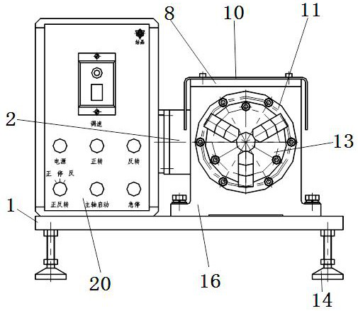
[0019] Such as Figure 1-Figure 3 As shown, a spiral pattern detector includes a base 1, and four adjustable feet 14 are installed on the lower end of the base 1, which is convenient for adjusting the level of the worktable. The main shaft part is fixed by bolts on the base 1, the main shaft part includes the main shaft case 16, the main shaft case 16 upper end is equipped with the main shaft case cover 8, the main shaft 9 is installed in the main shaft case 16, and the front end of the main shaft 9 is equipped with the front end bearing 15 , the outer ring of the front end bearing 15 is fastened together with the main shaft housing 16 through the main shaft front cover 11, the rear end of the main shaft 9 is equipped with a rear end bearing 17, and the outer ring of the rear end bearing 17 is tightly connected to the main shaft housing 16 through...


PUM


Abstract

The invention discloses a spiral thread detection method and a special instrument thereof, and the method comprises the steps: supporting an inner hole of a to-be-detected workpiece, coating a layer of thin mineral oil on the outer circle of a to-be-detected spiral thread, and hanging a heavy hammer through a cotton thread; enabling the to-be-detected workpiece to rotate anticlockwise, and if the cotton thread for hanging the heavy hammer does not move within one minute or the moving distance of the cotton thread along the axis is smaller than or equal to 5 mm, indicating that the to-be-detected workpiece does not have spiral threads; if the movement distance of the cotton thread along the axis is larger than 5 mm, indicating that spiral threads exist possibly, then enabling the to-be-detected workpiece to rotate clockwise, and if the cotton thread for hanging the heavy hammer moves in the reverse direction along the axis and in the forward rotation process within one minute, indicating that the to-be-detected workpiece does not have spiral threads; if the cotton thread for hanging the heavy hammer moves along the axis in the same direction as the forward rotation direction within one minute, indicating that the clamping of the to-be-detected workpiece is not horizontal, and the clamping of the to-be-detected workpiece needs to be readjusted. The special instrument is simple in structure, convenient to operate, stable, reliable and good in detection effect.

Description

technical field [0001] The invention relates to a spiral pattern detection method and a special instrument thereof, belonging to the technical field of mechanical detection. Background technique [0002] At present, during the cylindrical grinding process of the produced bearings and motor shafts, due to reasons such as vibration, excessive contact stiffness, and distortion of the geometric accuracy of the machine tool, spiral patterns will occur on the surface of the workpiece being ground by the cylindrical grinder. Occasionally, the spiral pattern can be distinguished by the naked eye, but most of them cannot be directly distinguished by the naked eye. There have been no good detection methods and equipment for many years, and only expensive precision instruments can be used for detection. The pitch and depth of the helical thread are used to determine whether the workpiece is qualified or not. The detection cost is high, but the detection efficiency is not high. Conten...

Claims


Application Information

Patent Timeline
Patent Type & Authority Applications(China)
IPC IPC(8): G01C9/12G01C9/24
CPCG01C9/12G01C9/24
Inventor 黄占波徐梁王鹏李光乐乔桂春
Owner 烟台轴仪精密仪器有限公司
Features
  • R&D
  • Intellectual Property
  • Life Sciences
  • Materials
  • Tech Scout
  • Unparalleled Data Quality
  • Higher Quality Content
  • 60% Fewer Hallucinations
Learn More