Steel rail drilling machine based on railway engineering

A technology of railway engineering and drilling machine, which is applied in the direction of boring/drilling, drilling/drilling equipment, metal processing machinery parts, etc., which can solve the problem of reducing drilling speed, increasing labor costs, and increasing the workload of repairing holes and other problems, to improve the drilling quality, prolong the service life, and reduce the effect of manpower consumption

Active Publication Date: 2021-10-19
ZHENGZHOU RAILWAY VOCATIONAL & TECH COLLEGE
View PDF10 Cites 2 Cited by
  • Summary
  • Abstract
  • Description
  • Claims
  • Application Information

AI Technical Summary

Problems solved by technology

[0002] Rail drilling machine refers to a type of drilling machine for on-site drilling of rails. It is one of the small machines commonly used in railway emergency maintenance operations. During the drilling process of rails, the drill bit must be pushed out frequently to eliminate cutting and cooling. To prevent cutting blockage or overheating of the drill bit or even breakage, and to make the drill bit evenly drilled, the existing rail drilling machine has two methods of manual drilling and mechanical drilling to control the feed drilling of the drilling machine. Move the joystick / hand handle, through the transmission system of worm gear, rack and pinion, drive the drill bit to feed or retract, and complete the rail drilling operation. Drilling in this way can ensure real-time feed and retract. The situation of cutting blockage is avoided, but workers often cannot maintain uniform force on the joystick / hand handle, and thus cannot ensure the uniform drilling of the drill bit. When the force is too large, the drilling amount will increase, wear or even damage the drill bit. If it is too small, the drilling rate will be reduced, the working time will be prolonged, and the workload of the workers will be increased. Manual feeding for a long time will also make the workers feel tired. At the same time, manual drilling generally requires two people to work together, that is, one person controls the drilling machine. Feed rate, another person cooperates with water supply cooling, which increases the labor cost; the existing mechanical drilling device generally uses rack and pinion drive / screw drive to drive the drill to feed the hole, but these two feed methods are controlled The drill bit feeds in the same direction for a long time, that is, the whole drilling process is only the feeding process. Although the mechanical drilling ensures the uniform drilling of the drill bit, the tool cannot be retracted during the drilling process, which can easily cause wear and breakage of the drill bit. , which greatly reduces the service life of the drill bit
[0003] Drilling should be slow at the beginning of drilling to prevent the drill bit from cracking, and when the hole is about to be drilled through, the amount of feed should also be reduced to avoid the vibration of the drill bit at the moment of drilling through, which will cause the phenomenon of "biting the knife" and make the exit irregular. , increase the workload of repairing holes, mechanical drilling cannot meet the above requirements, and manual drilling is time-consuming and laborious

Method used


Image

  • Steel rail drilling machine based on railway engineering
  • Steel rail drilling machine based on railway engineering
  • Steel rail drilling machine based on railway engineering

Examples


Embodiment 1

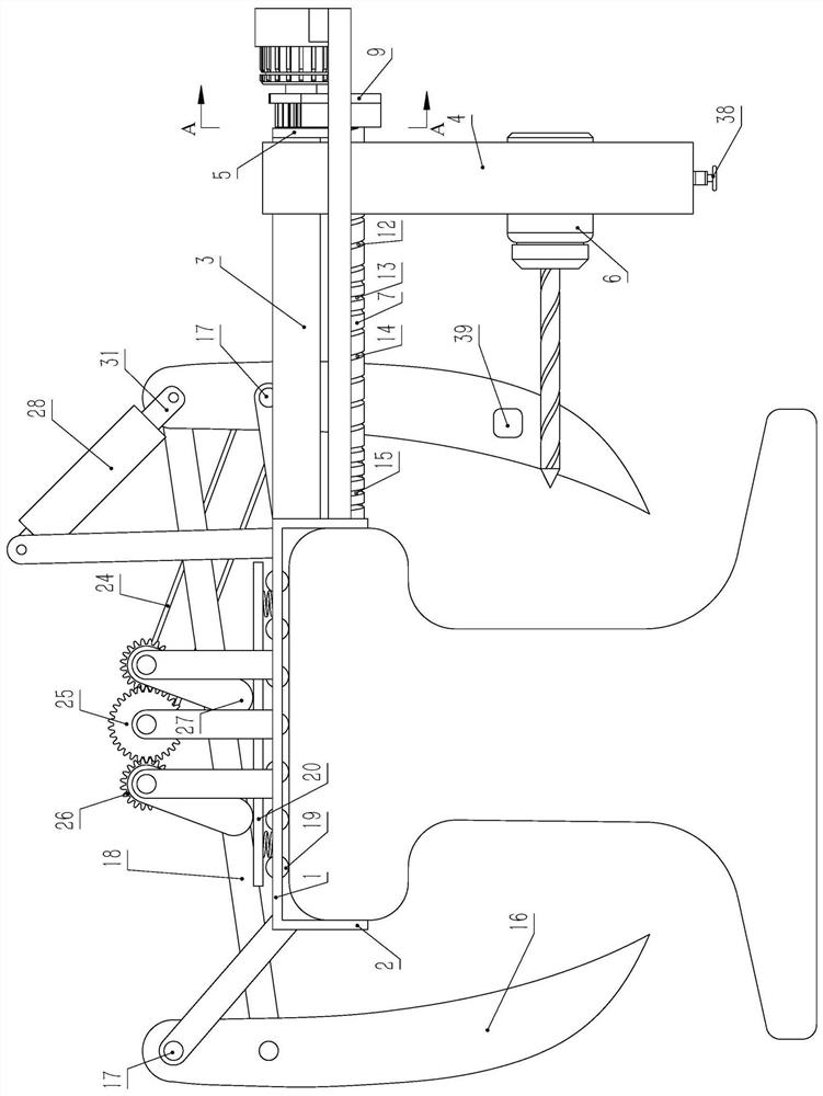
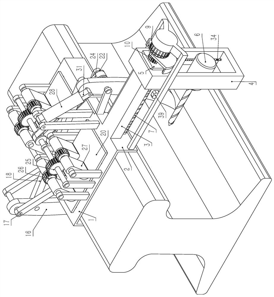
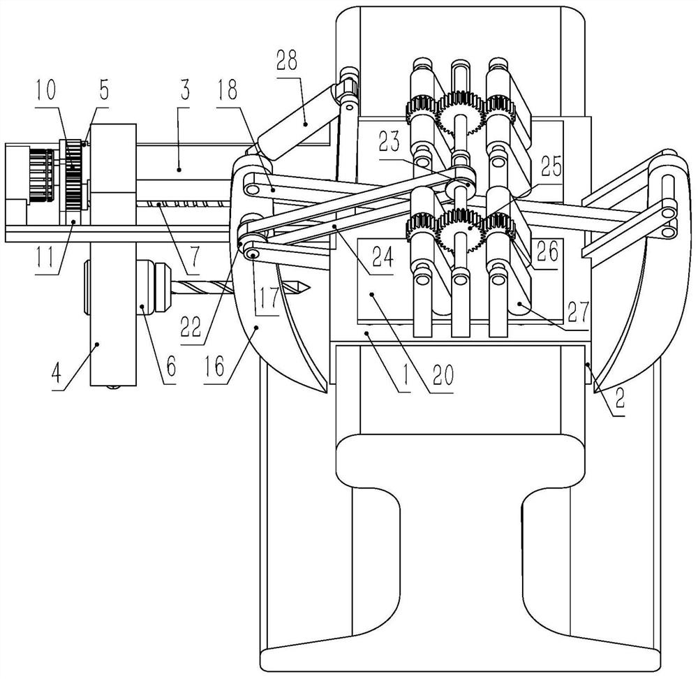
[0024]Embodiment 1. A rail drilling machine based on railway engineering, comprising a horizontal rail top abutment 1 arranged on the rail top, two rail top abutment 1 respectively placed on the left and right sides of the rail top abutment 1 The vertical limit side plate 2, the limit side plate 2 slides and fits with the rail head side of the rail, the rail top abutment 1 has a horizontally arranged guide strip 3 placed on the right side of the rail, and a vertical guide bar 3 is placed on the right side of the rail. The feed frame 4, the upper end of the feed frame 4 is slidingly sleeved on the guide bar 3, so that the feed frame 4 and the guide bar 3 are slidably connected in the transverse direction, and the right end of the guide bar 3 has a stop plate 5, and the limit The baffle plate 5 is used to limit the rightward movement of the feed frame 4. The feed frame 4 has a horizontally arranged drill 6 corresponding to the rail waist. The drill bit of the drill 6 faces the ra...

Embodiment 2

[0025] Embodiment 2, on the basis of Embodiment 1, the cam grooves include the first cam groove 12, the second cam groove 13, the third cam groove 14, the fourth cam groove 15, the first cam groove 12, the second cam groove 13 , the third cam groove 14, and the fourth cam groove 15 have the same rotation direction, and the first cam groove 12, the second cam groove 13, the third cam groove 14, and the fourth cam groove 15 are respectively spirally arranged along the axis of the feed column 7, The first cam groove 12 is placed on the right part of the feed column 7, the second cam groove 13 is placed on the left side of the first cam groove 12 and communicates with the left end of the first cam groove 12, and the third cam groove 14 is placed on the second The left side of the cam groove 13 communicates with the left end of the second cam groove 13, the fourth cam groove 15 is placed on the left side of the third cam groove 14 and communicates with the left end of the third cam ...

Embodiment 3

[0026] Embodiment 3, on the basis of Embodiment 1, the clamping device includes vertical jaws 16 opposite to the left and right sides of the rail, and the jaws 16 are provided with a first through hole whose axis is set along the front and rear directions , the first through hole on the jaw 16 on the left side of the rail is located above the first through hole on the jaw 16 on the right side of the rail, and the fixed shaft 17 is rotated in the first through hole, and the fixed shaft 17 is connected to the top of the rail. The abutments 1 are fixedly connected by pillars, forming a rotary connection between the jaws 16 and the rail top abutment 1. There is an inclined connecting rod 18 between the two jaws 16, and the left end of the connecting rod 18 is connected to the left side of the rail. The jaws 16 are hinged through the front and rear shafts, the right end of the connecting rod 18 is hinged with the jaws 16 on the right side of the rail through the front and rear shaft...


PUM


Abstract

The invention discloses a steel rail drilling machine based on railway engineering. The steel rail drilling machine effectively solves the problems that the existing steel rail drilling machine can only perform one-way feeding and is poor in adaptability during drilling, and controls the feeding amount and the retracting amount of a drill bit during drilling through meshing transmission among a sector gear, a gear and an arc-shaped gear ring. The feeding action of a drilling machine integrates the advantages of manual drilling and mechanical drilling, uniform drilling during drilling is guaranteed, drilling blockage caused by cutting is avoided, abrasion of a drill bit is reduced to the maximum extent, the service life of the drill bit is prolonged, the positioning process and the drilling process of the device are both automatically carried out, and operation is easy and convenient.

Description

technical field [0001] The invention relates to the technical field of railway engineering, in particular to a rail drilling machine based on railway engineering. Background technique [0002] Rail drilling machine refers to a type of drilling machine for on-site drilling of rails. It is one of the small machines commonly used in railway emergency maintenance operations. During the drilling process of rails, the drill bit must be pushed out frequently to eliminate cutting and cooling. To prevent cutting blockage or overheating of the drill bit or even breakage, and to make the drill bit evenly drilled, the existing rail drilling machine has two methods of manual drilling and mechanical drilling to control the feed drilling of the drilling machine. Move the joystick / hand handle, through the transmission system of worm gear, rack and pinion, drive the drill bit to feed or retract, and complete the rail drilling operation. Drilling in this way can ensure real-time feed and retr...

Claims


Application Information

Patent Timeline
Patent Type & Authority Applications(China)
IPC IPC(8): B23B41/00B23B47/20B23Q3/06B23Q11/10
CPCB23B41/00B23Q5/28B23Q3/06B23Q11/10
Inventor 谢小山吴钰马志芳黄莉唐华瑞陈晓红梁一星
Owner ZHENGZHOU RAILWAY VOCATIONAL & TECH COLLEGE
Why Eureka
Try Eureka