Construction method of spiral impact drilling device suitable for rock and soil

A construction method and drilling device technology, which are applied in the construction field of helical impact drilling devices, can solve the problems of increasing construction period, drilling inclination, and increasing engineering costs, so as to avoid deviation of drilling inclination, stable rotation frequency and transmission. System stabilization effect

Active Publication Date: 2021-03-16
DALIAN UNIV OF TECH
View PDF6 Cites 2 Cited by
  • Summary
  • Abstract
  • Description
  • Claims
  • Application Information

AI Technical Summary

Problems solved by technology

But, there are following problems in this type of solution: (1) the replacement, transportation, assembly, checking of machine tool equipment spend a lot of time, increase the construction period
(2) Replacing different drilling equipment according to different formation conditions will increase the engineering cost virtually
(3) The replacement and displacement of the machine tool may easily cause hole position deviation and drilling inclination

Method used


Image

  • Construction method of spiral impact drilling device suitable for rock and soil
  • Construction method of spiral impact drilling device suitable for rock and soil
  • Construction method of spiral impact drilling device suitable for rock and soil

Examples


Embodiment 1

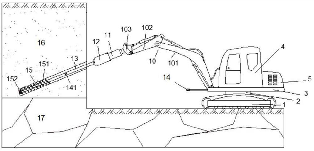
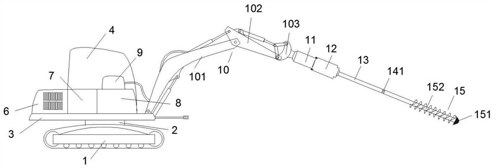
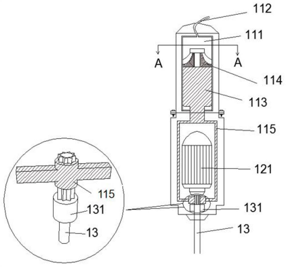
[0041] Such as figure 1As shown in -4, a construction method of a spiral percussion drilling device suitable for rock and soil, the drilling device includes a drilling rig system and a drilling rig support, and the drilling rig support includes a walking chassis mechanism 1, and the chassis mechanism 1 is equipped with a rotating Mechanism 2, the rotating mechanism 2 is provided with a working platform 3, the driving and operating room 4 is arranged on the working platform 3, the front end of the working platform 3 is provided with a boom 10, and the front end of the boom 10 is connected with the drilling system; the drilling system Including power distribution system, air pressure system 6, rock drilling parts 11, soil drilling parts 12, gears, drill pipe 13 and drill bit 15 at the bottom of the drill pipe; There is a cylinder 111, the top of the cylinder 111 is provided with an air pipe 112, the bottom of the cylinder 111 has a hole, and the cylinder 111 is provided with a p...


PUM


Abstract

The invention discloses a construction method of a spiral impact drilling device suitable for rock and soil. The drilling device comprises a drilling machine system and a drilling machine support, wherein the drilling machine support comprises a walking chassis mechanism, a rotating mechanism is arranged on the chassis mechanism, a working platform is arranged on the rotating mechanism, a drivingand operating room is arranged on the working platform, a movable arm is arranged at the front end of the working platform, and the front end of the movable arm is connected with the drilling system;and the drilling system comprises a power distribution system, an air compression system, a rock drilling component, a soil drilling component, a gear, a drill rod and a drill bit. The construction method comprises the steps of enabling the drilling machine support to travel to a designated position; installing a drilling system; adjusting the initial height and the drilling angle of the drill bit; and starting drilling. According to the construction method, the problem that drilling equipment cannot be suitable for different soil layers can be solved, and the method can adapt to different stratum conditions since the drilling angle can be accurately controlled and high maneuverability is achieved; moreover, the method is environmentally-friendly and can save energy and reduce noise; and in addition, the drill bit is firm and reliable, and therefore the method is suitable for slope and foundation pit supporting engineering.

Description

technical field [0001] The invention belongs to the technical field of geotechnical engineering, and in particular relates to a construction method of a spiral percussion drilling device suitable for rock and soil. Background technique [0002] Bolt support is a common form of support in the field of geotechnical engineering. Usually, the soil layer is drilled with an auger drill, and the rock layer is drilled with percussion down-the-hole drilling. In actual engineering, complex formations with both soil and rock formations are often encountered. The conventional solution to such problems is to replace drilling equipment. However, there are following problems in this type of solution: (1) the replacement, transportation, assembly, and check of machine tool equipment take a lot of time and increase the construction period. (2) Replacement of different drilling equipment according to different formation conditions will increase the engineering cost virtually. (3) The replac...

Claims


Application Information

Patent Timeline
Patent Type & Authority Applications(China)
IPC IPC(8): E21B6/04E21B7/02E21B7/04E21B15/04E21B19/18E21B10/00E21B17/042
CPCE21B6/04E21B7/02E21B7/04E21B10/00E21B15/04E21B17/042E21B19/18
Inventor 陈湘生高幸贾金青张丽华涂兵雄廖小平朱彦鹏王旭春周同和
Owner DALIAN UNIV OF TECH
Why Eureka
Try Eureka