A rail drilling machine based on railway engineering
A technology of railway engineering and drilling machine, which is applied in the direction of boring/drilling, drilling/drilling equipment, metal processing machinery parts, etc. and other problems to achieve the effect of improving drilling quality, prolonging service life and reducing labor consumption
- Summary
- Abstract
- Description
- Claims
- Application Information
AI Technical Summary
Problems solved by technology
Method used
Image
Examples
Embodiment 1
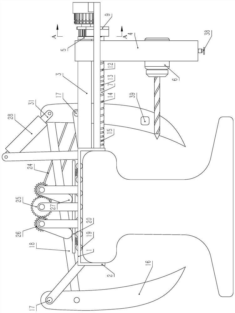
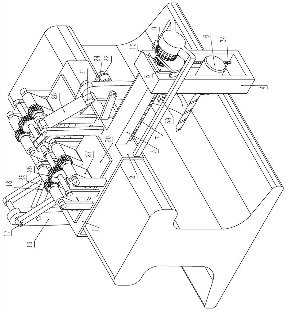
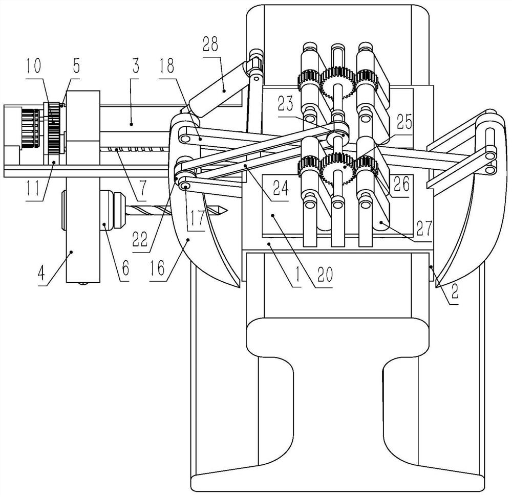
[0024]Embodiment 1. A rail drilling machine based on railway engineering, comprising a horizontal rail top abutment 1 arranged on the rail top, two rail top abutment 1 respectively placed on the left and right sides of the rail top abutment 1 The vertical limit side plate 2, the limit side plate 2 slides and fits with the rail head side of the rail, the rail top abutment 1 has a horizontally arranged guide strip 3 placed on the right side of the rail, and a vertical guide bar 3 is placed on the right side of the rail. The feed frame 4, the upper end of the feed frame 4 is slidingly sleeved on the guide bar 3, so that the feed frame 4 and the guide bar 3 are slidably connected in the transverse direction, and the right end of the guide bar 3 has a stop plate 5, and the limit The baffle plate 5 is used to limit the rightward movement of the feed frame 4. The feed frame 4 has a horizontally arranged drill 6 corresponding to the rail waist. The drill bit of the drill 6 faces the ra...
Embodiment 2
[0025] Embodiment 2, on the basis of Embodiment 1, the cam grooves include the first cam groove 12, the second cam groove 13, the third cam groove 14, the fourth cam groove 15, the first cam groove 12, the second cam groove 13 , the third cam groove 14, and the fourth cam groove 15 have the same rotation direction, and the first cam groove 12, the second cam groove 13, the third cam groove 14, and the fourth cam groove 15 are respectively spirally arranged along the axis of the feed column 7, The first cam groove 12 is placed on the right part of the feed column 7, the second cam groove 13 is placed on the left side of the first cam groove 12 and communicates with the left end of the first cam groove 12, and the third cam groove 14 is placed on the second The left side of the cam groove 13 communicates with the left end of the second cam groove 13, the fourth cam groove 15 is placed on the left side of the third cam groove 14 and communicates with the left end of the third cam ...
Embodiment 3
[0026] Embodiment 3, on the basis of Embodiment 1, the clamping device includes vertical jaws 16 opposite to the left and right sides of the rail, and the jaws 16 are provided with a first through hole whose axis is set along the front and rear directions , the first through hole on the jaw 16 on the left side of the rail is located above the first through hole on the jaw 16 on the right side of the rail, and the fixed shaft 17 is rotated in the first through hole, and the fixed shaft 17 is connected to the top of the rail. The abutments 1 are fixedly connected by pillars, forming a rotary connection between the jaws 16 and the rail top abutment 1. There is an inclined connecting rod 18 between the two jaws 16, and the left end of the connecting rod 18 is connected to the left side of the rail. The jaws 16 are hinged through the front and rear shafts, the right end of the connecting rod 18 is hinged with the jaws 16 on the right side of the rail through the front and rear shaft...
PUM
 Abstract
Description
Claims
Application Information
 - R&D
- Intellectual Property
- Life Sciences
- Materials
- Tech Scout
- Unparalleled Data Quality
- Higher Quality Content
- 60% Fewer Hallucinations
Browse by: Latest US Patents, China's latest patents, Technical Efficacy Thesaurus, Application Domain, Technology Topic, Popular Technical Reports.
© 2025 PatSnap. All rights reserved.Legal|Privacy policy|Modern Slavery Act Transparency Statement|Sitemap|About US| Contact US: help@patsnap.com


