Supercharge Your Innovation With Domain-Expert AI Agents!

PCB polishing device for intelligent manufacturing

A PCB board and polishing device technology, which is applied in the direction of manufacturing tools, grinding drive devices, surface polishing machine tools, etc., can solve the problems of too much or too little polishing, affecting the polishing quality of the PCB side surface, and poor fixing effect

Active Publication Date: 2021-10-19
陈丽虹
View PDF10 Cites 0 Cited by
  • Summary
  • Abstract
  • Description
  • Claims
  • Application Information

AI Technical Summary

Problems solved by technology

[0004] In order to overcome the problem that the polishing quality of the side surface of the PCB board may be affected due to the poor fixing effect when the existing PCB board is polished, and at the same time, poor control of the polishing process will lead to too much or too little polishing, which will affect the qualified rate of the PCB board quality Disadvantages, the technical problem of the present invention is to provide a PCB board polishing device for intelligent manufacturing that can be clamped and fixed, and can adjust and control the precise polishing of PCB boards and can quickly discharge materials.

Method used


Image

  • PCB polishing device for intelligent manufacturing
  • PCB polishing device for intelligent manufacturing
  • PCB polishing device for intelligent manufacturing

Examples


Embodiment 1

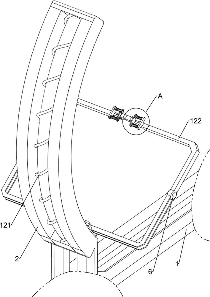
[0075] A kind of PCB board polishing device for intelligent manufacturing, such as Figure 1-4 As shown, it includes a bottom plate 1, a first slide rail 2, a first slide bar 3, a first movable block 4, a biaxial motor 5, a first support frame 6, a friction disc 7, a first belt 8, a rotating mechanism 9 and Clamping mechanism 10, bottom plate 1 upper front side is provided with first slide rail 2, and first slide rail 2 is provided with first slide bar 3, and first slide bar 3 is provided with first movable block 4 slidingly, and first The rear side of the movable block 4 is equipped with a biaxial motor 5, and the left and right sides of the first movable block 4 are symmetrically provided with a first support frame 6, and the rear sides of the two first support frames 6 are all rotatably provided with a friction disc 7, and the biaxial motor 5 A first belt 8 is connected between the output shafts on the left and right sides and the friction disc 7 on the same side through a ...

Embodiment 2

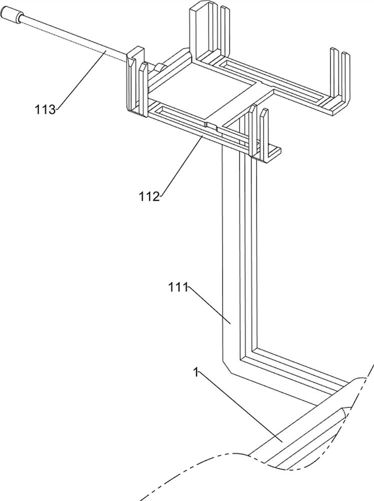
[0082] On the basis of Example 1, such as figure 1 , Figure 5-10 As shown, a pusher mechanism 11 is also included, and the pusher mechanism 11 includes a fourth support frame 111, a material receiving frame 112 and a first push plate 113, and the left side of the bottom plate 1 is provided with a fourth support frame 111, and the fourth The top of the support frame 111 is provided with a receiving frame 112 , and the lower part of the left side of the receiving frame 112 is slidably provided with a first push plate 113 , and the first push plate 113 cooperates with the pressing plate 102 .

[0083] People first put the PCB board to be polished on the receiving frame 112, and then people manually push the first push plate 113 to the right, and the first push plate 113 will drive the PCB board to move to the right, and then manually pull the pressure plate 102 to move upward, so that The PCB board is located between the supporting plate 96 and the pressing plate 102, so as to ...


PUM


Abstract

The invention relates to a polishing device, in particular to a PCB polishing device for intelligent manufacturing. The invention provides the PCB polishing device for intelligent manufacturing, which has the advantages that clamping and fixing can be realized, accurate polishing of a PCB can be adjusted and controlled, and rapid discharging can be realized. The PCB polishing device for intelligent manufacturing comprises a base plate, a first sliding rail, a first sliding rod, a first movable block, a double-shaft motor and first supporting frames, wherein the first sliding rail is arranged on the base plate, the first sliding rod is arranged in the first sliding rail, the first movable block is arranged on the first sliding rod in a sliding mode, the double-shaft motor is arranged on the first movable block, and the first supporting frames are symmetrically arranged on the two sides of the first movable block. According to the PCB polishing device, a rotating mechanism is arranged, a supporting plate rotates to drive the PCB to rotate, the PCB is turned over to the position between two friction discs, the friction discs polish the PCB, and the rapid and uniform polishing effect is achieved; and a clamping mechanism is arranged, and a pressing plate moves downwards to press and fix the PCB, so that the clamping effect is achieved.

Description

technical field [0001] The invention relates to a polishing device, in particular to a PCB board polishing device for intelligent manufacturing. Background technique [0002] The Chinese name of PCB is printed circuit board, also known as printed circuit board. It is an important electronic component, a support for electronic components, and a carrier for electrical connections of electronic components. Because it is made by electronic printing, it is called a "printed" circuit board; because a printed circuit board is not a general end product, the definition of the name is slightly confusing, for example: a motherboard for a personal computer is called a motherboard , and cannot be directly called a circuit board. Although there are circuit boards in the motherboard, they are not the same. Therefore, when evaluating the industry, the two are related but cannot be said to be the same. At present, after the PCB board is produced and cut, the side surface of the PCB board is...

Claims


Application Information

Patent Timeline
Patent Type & Authority Applications(China)
IPC IPC(8): B24B29/02B24B41/04B24B41/06B24B47/12B24B47/22
CPCB24B29/02B24B41/04B24B47/12B24B41/06B24B47/22
Inventor 陈丽虹
Owner 陈丽虹
Features
  • R&D
  • Intellectual Property
  • Life Sciences
  • Materials
  • Tech Scout
  • Unparalleled Data Quality
  • Higher Quality Content
  • 60% Fewer Hallucinations
Learn More