Supercharge Your Innovation With Domain-Expert AI Agents!

Deep sludge foundation treatment structure and treatment method thereof

A foundation treatment and treatment method technology, which is applied in foundation structure engineering, soil protection, construction, etc., can solve the problems of unstable pile quality, thick silt layer, large deformation, etc., and achieve the effect of preventing internal structure water seepage

Active Publication Date: 2021-10-19
江苏瑞沃建设集团有限公司
View PDF7 Cites 0 Cited by
  • Summary
  • Abstract
  • Description
  • Claims
  • Application Information

AI Technical Summary

Problems solved by technology

[0002] When the silt layer at the part where the foundation needs to be laid is thick and it is difficult to carry out deep treatment on a large area, piling methods can be used for reinforcement treatment; there are various pile foundation technologies, and cement-soil mixing piles, sand and gravel piles, and wooden piles were mostly used in the early days. Rarely used, one is that the control and management automation system of cement-soil mixing piles such as water-cement ratio, slurry volume and mixing times is not perfect, the equipment is outdated, the technology is backward, and there are problems of poor mixing uniformity and unstable pile quality
[0003] The current foundation treatment structure has the problems of long construction period and large deformation after completion of the deep silt soft soil foundation; there is the problem of easy water seepage inside the foundation

Method used


Image

  • Deep sludge foundation treatment structure and treatment method thereof
  • Deep sludge foundation treatment structure and treatment method thereof
  • Deep sludge foundation treatment structure and treatment method thereof

Examples


Embodiment Construction

[0020] The following will clearly and completely describe the technical solutions in the embodiments of the present invention with reference to the accompanying drawings in the embodiments of the present invention. Obviously, the described embodiments are only some, not all, embodiments of the present invention. Based on the embodiments of the present invention, all other embodiments obtained by persons of ordinary skill in the art without making creative efforts belong to the protection scope of the present invention.

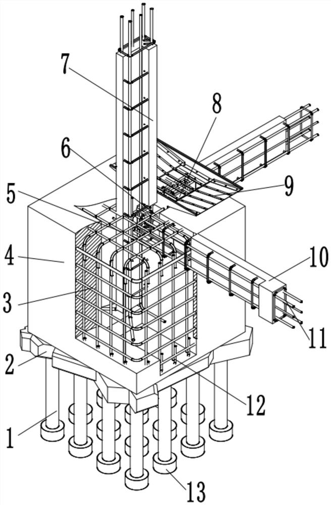
[0021] see Figure 1-4 , in an embodiment of the present invention, a deep silt foundation treatment structure and treatment method thereof, including a silt adsorption reinforcement device 13, the upper end surface of the silt adsorption reinforcement device 13 is connected to a pile foundation 1 by cement pouring, and the other side of the pile foundation 1 is installed There is a cement middle slab 2, the upper end of the cement middle slab 2 is fixedly ins...


PUM


Abstract

The invention discloses a deep sludge foundation treatment structure and a treatment method thereof, and relates to the field of buildings. The deep sludge foundation treatment structure comprises a sludge adsorption reinforcing device, wherein the upper end surface of the sludge adsorption reinforcing device is connected with a pile foundation through cement pouring; a cement middle-layer plate is mounted on the other side of the pile foundation; a concrete prefabricated main foundation is fixedly mounted at the upper end of the cement middle-layer plate; reinforcing transverse steel penetrates through the inner side of the concrete prefabricated main foundation; cement pouring areas are arranged on the two sides of the concrete prefabricated main foundation; water pumping grooves are fixedly mounted in the upper end surfaces of the cement pouring areas; ground temporary supporting devices are welded at the upper ends of the water pumping grooves; a vertical concrete frame is fixedly mounted on the upper end surface of the concrete prefabricated main foundation; a horizontal concrete frame is fixedly mounted on the right side of the concrete prefabricated main foundation; an outward-extending supporting reinforcing device is arranged on the inner side of the horizontal concrete frame through cement pouring; and a prefabricated ground hook is mounted at the upper end of the cement middle-layer plate. The deep sludge foundation treatment structure has the advantages that stable and deep foundation construction is carried out in a sludge area, and stable support is provided for a building.

Description

technical field [0001] The invention relates to the construction field, in particular to a deep silt foundation treatment structure and a treatment method thereof. Background technique [0002] When the silt layer at the part where the foundation needs to be laid is thick and it is difficult to carry out deep treatment on a large area, piling methods can be used for reinforcement treatment; there are various pile foundation technologies, and cement-soil mixing piles, sand and gravel piles, and wooden piles were mostly used in the early days. It is rarely used. First, the control and management automation system of cement-soil mixing piles such as water-cement ratio, slurry volume and mixing times is not perfect, the equipment is outdated, the technology is backward, and there are problems of poor mixing uniformity and unstable pile quality. [0003] The current foundation treatment structure has the problems of long construction period and large deformation after completion ...

Claims


Application Information

Patent Timeline
IPC IPC(8): E02D3/00E02D3/10E02D5/34E02D27/12
CPCE02D3/00E02D3/10E02D5/34E02D27/12
Inventor 张金生徐新文戴伟吉开学陈小虎陈全龙
Owner 江苏瑞沃建设集团有限公司
Features
  • R&D
  • Intellectual Property
  • Life Sciences
  • Materials
  • Tech Scout
  • Unparalleled Data Quality
  • Higher Quality Content
  • 60% Fewer Hallucinations
Learn More