Tuning vibration absorption device

A technology of constrained layers and connectors, which is applied to building components, earthquake resistance, etc., can solve the problem that tuned mass dampers cannot handle high-frequency vibrations of building structures well

Active Publication Date: 2021-10-19
TONGJI UNIV +1
View PDF7 Cites 0 Cited by
  • Summary
  • Abstract
  • Description
  • Claims
  • Application Information

AI Technical Summary

Problems solved by technology

[0006] In view of the problem that the tuned mass damper and constrained damping treatment in the prior art cannot handle the high-fre

Method used


Image

  • Tuning vibration absorption device
  • Tuning vibration absorption device
  • Tuning vibration absorption device

Examples


Embodiment 1

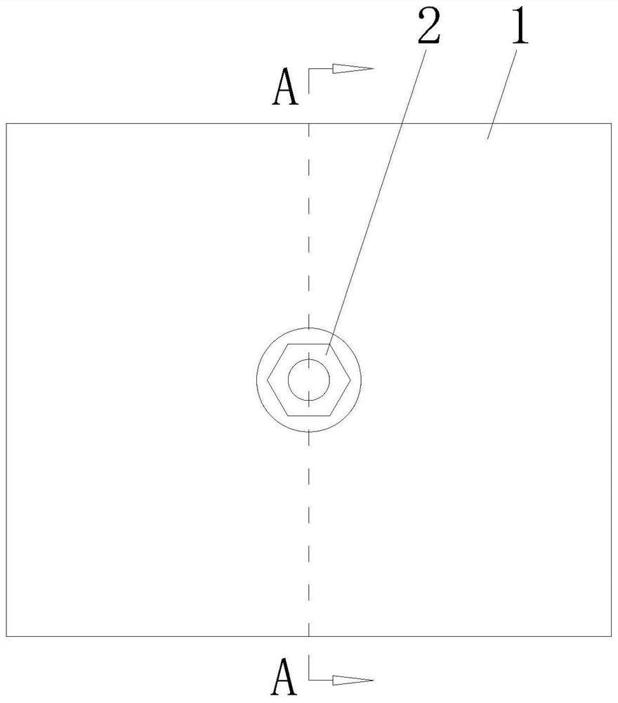
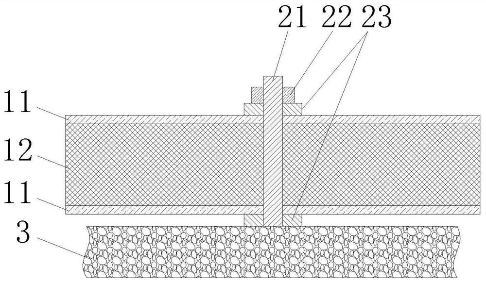
[0033] A tuned vibration absorbing device such as figure 1 and figure 2 As shown, it includes a vibration-absorbing unit 1 and a connection structure 2 for connecting the vibration-absorbing unit 1 .

[0034] Wherein, the vibration-absorbing unit 1 includes two oppositely arranged constrained layers 11 and a constrained layer 12 sandwiched between the two constrained layers 11, the constrained layer 12 is made of a damping material, such as high damping polyurethane or rubber, and the constrained layer 11 is usually made of rigid material, such as steel or aluminum alloy. Moreover, the constrained layer 11 and the constrained layer 12 are closely connected, for example, by adhesive bonding, so as to avoid slippage between the two.

[0035] The connecting structure 2 includes connecting pieces 21 , fasteners 22 and gaskets 23 . Wherein, the gasket 23 has a through hole so as to be sleeved on the connector 21, and the gasket 23 is arranged on both sides of the vibration-abso...

Embodiment 2

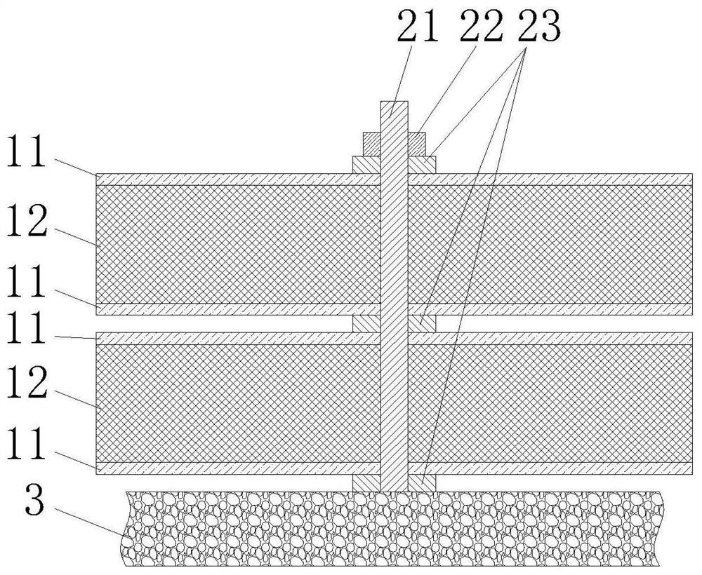
[0040] The difference between it and Embodiment 1 is: in this embodiment, if image 3 As shown, there are multiple (two or more) vibration-absorbing elements 1, and multiple vibration-absorbing elements 1 are stacked. There are gaps between the vibration-absorbing elements 1, so as to provide sufficient deformation space.

[0041] It can be understood that the arrangement of multiple vibration-absorbing elements 1 can improve the vibration-absorbing efficiency on the one hand, so that the vibration energy on the controlled structure 3 can be converted into heat energy by more vibration-absorbing elements 1, improving the vibration-absorbing efficiency; Adjust the size of each vibration-absorbing element 1 and the relationship between the thickness of each layer, so that each vibration-absorbing element 1 has a different frequency, so that the device has a larger vibration-absorbing frequency band, which is suitable for the vibration of each frequency that occurs on the control...

Embodiment 3

[0043] The difference between it and Embodiment 1 is: in this embodiment, if Figure 4 and Figure 5 As shown, the perforation 13 is elongated, so that a plurality of the above-mentioned connectors 21 are arranged at intervals in the perforation 13 along its length direction. The through hole that the connector 21 is compatible with. Moreover, when the vibration-absorbing element 1 is configured as a rectangle, the length direction of the through hole 13 is parallel to the side of the vibration-absorbing element 1 .

[0044] It can be understood that the through holes 13 may be integrally provided on the vibration absorbing element 1 , that is, the three layers of the vibration absorbing element 1 are provided with the through holes 13 opposite to each other. Such setting, on the one hand, enables the vibration on the controlled structure 3 to be more efficiently transmitted to the vibration-absorbing element 1; The setting of the component 21 makes the vibration absorbing ...


PUM


Abstract

The invention discloses a tuning vibration absorption device, and belongs to the technical field of vibration absorption. The tuning vibration absorption device comprises at least one vibration absorption element and a connecting structure for connecting the at least one vibration absorption element; the vibration absorption element comprises two oppositely arranged restraint layers and a restrained layer clamped between the two restraint layers, and the restrained layer is made of a damping material; and the connecting structure comprises a connecting piece, a fastening piece and gaskets, the gaskets are arranged on the connecting piece in a sleeving mode, the gaskets are arranged on the two sides of each vibration absorption element, and the fastening piece is fixed to the connecting piece so as to fix the vibration absorption elements when the connecting piece is fixed to a controlled structure to be used. The vibration absorption element is far away from the controlled structure, so that after vibration on the controlled structure is transmitted to the vibration absorption element through the connecting piece, the vibration absorption element has sufficient deformation space, the deformation of the part, far away from the connecting piece, of the vibration absorption element is larger, and therefore high-frequency vibration is efficiently subjected to vibration absorption treatment.

Description

technical field [0001] The invention relates to the technical field of shock absorption, in particular to a tuned shock absorbing device. Background technique [0002] The vibration of 1-100 Hz generated by the operation of equipment such as floor and wall panels of building structures will cause vibration comfort problems, and the vibration of 20-500 Hz will be accompanied by solid noise, which will affect people's health or comfort. Tuning vibration absorption through a tuned mass damper (TMD for short), or absorbing and reducing vibration through a constrained damping structure is the main idea of ​​vibration reduction at present. [0003] Tuned mass dampers traditionally used in buildings use coil springs or leaf springs as elastic elements, and polymers or viscous liquids as damping materials to form a spring-mass-damper system to tune and control the vibration of the structure. For example, the Chinese utility model patent with the notification number CN211499274U dis...

Claims


Application Information

Patent Timeline
IPC IPC(8): E04B1/98
CPCE04B1/98
Inventor 孙飞飞尹文汉褚濛李国强丁振坤金华建王波董飞曹舟龚琪
Owner TONGJI UNIV
Why Eureka
Try Eureka