Multi-pose charger and shell

A charger, multi-position technology, applied in the direction of current collectors, electric vehicles, electrical components, etc., can solve the problems of increased control lines, clumsy and laborious turning, inconvenient to carry, etc., to achieve height improvement, easy to use, easy to carry and travel Effect

Inactive Publication Date: 2020-08-21
DALIAN WHIM SCI & TECH LTD CO
View PDF0 Cites 0 Cited by
  • Summary
  • Abstract
  • Description
  • Claims
  • Application Information

AI Technical Summary

Problems solved by technology

In order to be able to charge horizontally and vertically at the same time, the mobile phone needs to be made very long, and two coils must be installed inside, and the control circuit is increased, which makes the volume and weight large and inconvenient to carry
In addition, the flip positioning structure of the flip bracket adopts a metal structure, which is heavy and costly, and it is clumsy and laborious to flip

Method used


Image

  • Multi-pose charger and shell
  • Multi-pose charger and shell
  • Multi-pose charger and shell

Examples


Embodiment 1

[0065] With the development of technology and technological progress, the interface form of the USB universal serial bus for mobile phone chargers and data transmission has undergone changes in versions 1.0, 2.0, and 3.0, and then developed more compact mini USB and micro USB interfaces with more functions. Powerful TYPE-C interface, there are A type, B type, AB type and C type respectively, the USB interface hardware is divided into female seat and male head, the principle of each type of USB interface is the same, for the convenience of expression, the present invention Take the disk-shaped wireless charger and typical USB2.0 and USB Type-C interfaces as examples for illustration.

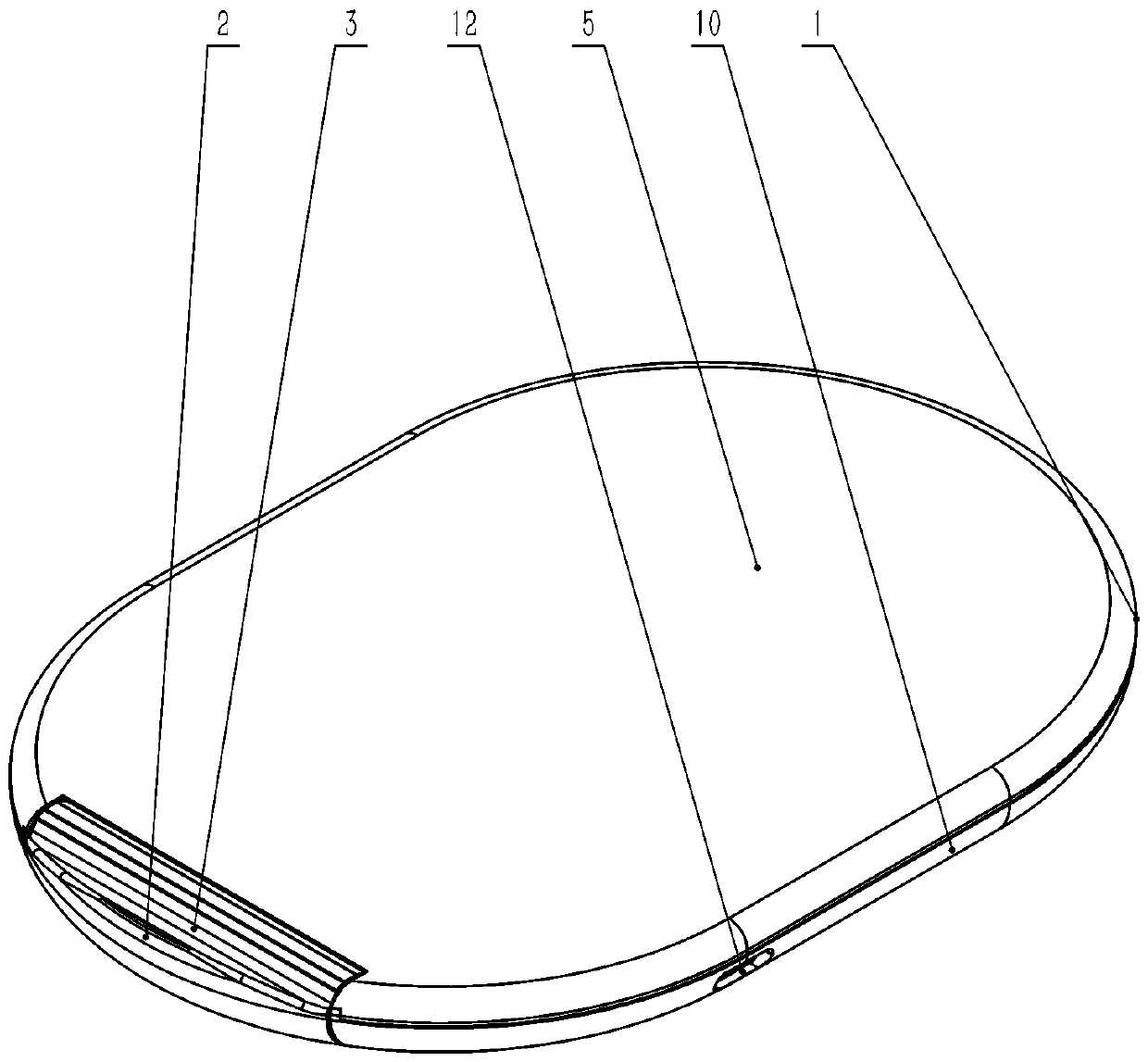
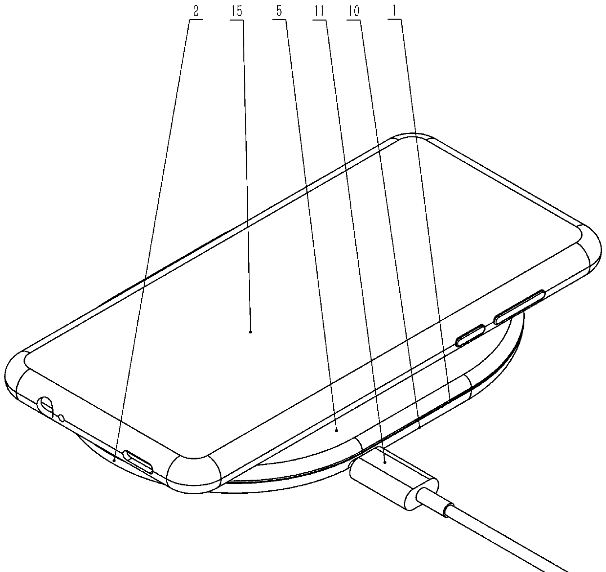
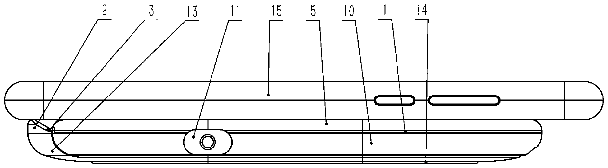
[0066] The wireless charger 1 is composed of an upper cover 5 , a lower case 10 and an internal wireless charging control circuit board, and is powered by a USB interface 11 .

[0067] Such as figure 1 and figure 2 Shown is a kind of racetrack-shaped multi-position charger shell of the present...

Embodiment 2

[0078] In order to realize vertical charging, the above-mentioned racetrack-shaped charger needs to be provided with dual coils and chips and PCB circuit boards supporting dual coil charging. At the same time, the overall length also needs to be very long, and the cost is relatively high.

[0079] The invention provides a structural proposal that a single-coil small disk charger can also be charged upright.

[0080] Such as Figure 11 and Figure 12 As shown, the overall shape of the aforementioned multi-position charger is disc-shaped, and a slideway 28 is provided in the lower case 10, and a telescopic frame 9 that can be stretched is arranged in the slideway. As shown in Figure 11, a slideway 28 is set at the corresponding position of the lower shell 10 and the telescopic plate 21, surrounded by baffles 29, the telescopic plate 21 can slide in the slideway 28 of the lower shell 10, and the corresponding position of the upper cover 5 A slideway 28 may also be provided. Lo...

Embodiment 3

[0086] Such as Figure 20 , Figure 21 and Figure 22 As shown, the aforementioned wireless charger can also be a convenient charger, that is, a circular groove and a circular groove are arranged on the upper surface of the upper cover 5 of the charger 1, and are respectively embedded in the inner pole plate 6 and the outer ring pole. Plate 8, the circular inner pole plate 6 is arranged on the inside, and the annular outer ring pole plate 8 is arranged on the outside, forming a concentric circle structure. The inner pole plate 6 and the outer ring pole plate 8 are materials with good conductivity, such as copper, silver, gold , stainless steel, aluminum, iron, zinc, tin, or the coating material of the above-mentioned metal plating on the surface. An isolation strip 7 is provided between the inner pole plate 6 and the outer ring pole plate 8 to keep them insulated from each other. Isolation strip 7 is an insulating material, such as plastics. The inner plate 6 and the outer...


PUM


Abstract

The invention provides a multi-pose charger and a shell. The shell comprises an upper cover 5, a lower shell 10 and a USB interface 12, wherein notches are formed in one ends of the upper cover 5 andthe lower shell 10, a base 13 is hinged in the notch of the lower shell 10, a rotating shaft seat 23 protruding upwards is arranged at the front end of the base 13, a shaft hole 24 is formed in the rotating shaft seat 23, a transversely-through positioning groove 3 is formed in the middle of the upper surface of a base cover 2 at the upper portion of the base 13, a sliding channel 28 is arranged in the lower shell 10, and is slidably connected with a telescopic frame 9; telescopic plates 21 are arranged on the two sides of the telescopic frame 9, a connecting rib 20 is arranged in the middle of the telescopic frame 9, an overturning shaft 17 is arranged at one end of the telescopic plate 21, the overturning shaft 17 is hinged to a shaft hole 24 in the rotating shaft seat 23, the telescopicframe 9 and the rotating shaft seat 23 are provided with positioning and locking structures, and a charging coil, a PCB control circuit board or a conducting wire is arranged in the shell. Accordingto the invention, the multi-posture charger is formed, a mobile phone can be horizontally, transversely and vertically charged, and use is free and convenient.

Description

technical field [0001] The invention relates to the field of wireless communication and electrical appliances and the field of mobile phone charging, in particular to a home appliance charger and a mobile phone charger. Background technique [0002] Wireless charging is indeed much more convenient than wired charging. Most of the current wireless chargers have a disc-shaped base, and the mobile phone is placed flat in the center of the disc for charging. There are also a few square chargers with a foldable bracket in the middle. X-shaped bracket, the mobile phone can be placed horizontally and obliquely, and you can charge the mobile phone while looking at the screen horizontally. In order to be able to charge horizontally and vertically at the same time, the mobile phone needs to be made very long, and two coils are installed inside, and the control circuit is increased, which makes the volume heavy and inconvenient to carry. In addition, the flip positioning structure of ...

Claims


Application Information

Patent Timeline
Patent Type & Authority Applications(China)
IPC IPC(8): H02J7/00H04M1/04
CPCH02J7/0044H04M1/04
Inventor 刘忠臣
Owner DALIAN WHIM SCI & TECH LTD CO
Why Eureka
Try Eureka