Simulation optimization design method for hot-blowing snow-removing exhaust device of turbofan engine

A turbofan engine and exhaust device technology, applied in computer-aided design, design optimization/simulation, calculation, etc., can solve the problems of increasing the cost of jet snow removal vehicles, small effective exhaust width, and inability to achieve fast snow removal, etc., to achieve Improve the effect of blowing snow and melting ice, reduce the amount of optimization calculation, and improve the effect of snow removal efficiency

Active Publication Date: 2021-10-19
甘肃长城氢能源工程研究院有限公司 +1
View PDF6 Cites 2 Cited by
  • Summary
  • Abstract
  • Description
  • Claims
  • Application Information

AI Technical Summary

Problems solved by technology

Therefore, the snow blowing and deicing device modified by the turbojet engine can basically meet the snow removal requirements of moderate to heavy snow in terms of function, but due to the small flow of the turbojet engine, it will be affected by the exhaust flow in the case of heavy snow. The limitation of snow removal results in low snow removal efficiency, which cannot meet the requirements of fast snow removal;
[0006]2. Exhaust device design method: conduct simulation optimization simulation for the size of exhaust velocity effective zone and exhaust velocity dead zone at the outlet of exhaust device, so as to optimize flow path The design of the cross-sectional area will lead to a better effect of the designed exhaust device on blowing snow, but due to the lack of consideration of the evolution process and spatial distribution of the exhaust temperature in the external flow field, it may occur when deicing the road surface The problem of the ice layer being difficult to melt effectively
At the same time, for asphalt ground, there may be a problem of road surface damage due to local excessive exhaust temperature;
[0007]3. Structural features of the exhaust device: the outlet section of the main nozzle and the opening nozzle is mostly designed with a circular section nozzle, and its biggest feature is that the structure is simple to manufacture , there is no need for a round-to-square transition section, but the effective exhaust width of the outlet is smaller, which reduces the snow blowing efficiency, causes some high-energy gas waste, and increases the cost of the jet snow removal vehicle

Method used


Image

  • Simulation optimization design method for hot-blowing snow-removing exhaust device of turbofan engine
  • Simulation optimization design method for hot-blowing snow-removing exhaust device of turbofan engine
  • Simulation optimization design method for hot-blowing snow-removing exhaust device of turbofan engine

Examples


specific Embodiment approach

[0083] It should be noted that the structures, proportions, sizes, etc. shown in this specification are only used to cooperate with the content disclosed in the specification for the understanding and reading of those familiar with this technology, and are not used to limit the conditions for the implementation of the present invention , any modification of structure, change of proportional relationship or adjustment of size shall still fall within the scope covered by the technical content disclosed in the present invention without affecting the effect and purpose of the present invention. .

[0084] At the same time, terms such as "upper", "lower", "left", "right", "middle" and "one" quoted in this specification are only for the convenience of description and are not used to limit the scope of this specification. The practicable scope of the invention and the change or adjustment of its relative relationship shall also be regarded as the practicable scope of the present inve...

Embodiment 1

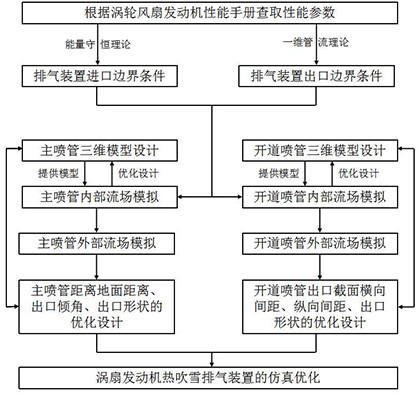
[0086] Such as figure 1 As shown, the invention discloses a simulation optimization design method of a turbofan engine thermal blowing snow removal exhaust device, comprising the following steps:

[0087] Step 1: Determine the inlet boundary conditions and outlet boundary conditions of the thermal blowing snow removal exhaust device based on the turbofan engine modification; check the performance parameters according to the turbofan engine performance manual, and then determine the inlet boundary conditions of the exhaust device through the energy conservation theory, Determine the outlet boundary conditions of the exhaust device according to the one-dimensional pipe flow theory;

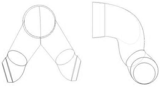
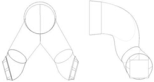
[0088] Step 2: Design the three-dimensional solid model of the main nozzle under different outlet cross-sectional shapes; that is, the three-dimensional model design of the main nozzle;

[0089] Step 3: According to the inlet boundary conditions and outlet boundary conditions described in step 1 an...

Embodiment 2

[0098] Preferably, the step 1 is specifically:

[0099] Step 1-1: Check the performance parameters according to the performance manual of the turbofan engine, and the performance parameters include: bypass ratio, total air flow, internal temperature, external temperature, total inlet pressure of the turbine, and drop-off pressure of the turbine under different working conditions specific and intrinsic pressure;

[0100] Step 1-2: According to the relationship between the bypass ratio and the total air flow, determine the internal air flow and the external air flow; according to the internal air flow, external air flow, internal temperature, external temperature, and ideal gas energy conservation theory, Determine the outlet temperature of the internal and external mixer, that is, the total temperature of the exhaust device inlet (equivalent to the total temperature in the exhaust device inlet boundary conditions); The pressure characteristic diagram of the internal and extern...


PUM


Abstract

The invention belongs to the technical field of simulation optimization of exhaust devices, and discloses a simulation optimization design method for a hot blowing snow removal exhaust device of a turbofan engine. Inlet and outlet boundary conditions of the exhaust device are determined based on the characteristics of the turbofan engine and a one-dimensional pipe flow theory; the current situation that a current hot blowing snow removal exhaust device is modified based the a turbojet engine is broken through, the inlet boundary condition of the exhaust device when an inner duct and an outer duct are mixed is accurately obtained, it is guaranteed that the exhaust device is in a critical or supercritical state, and the engine performance is fully utilized.

Description

technical field [0001] The invention belongs to the technical field of simulation optimization of exhaust devices, and in particular relates to a simulation optimization design method of thermal blowing and snow removal exhaust devices of turbofan engines. Background technique [0002] At present, the main method of quickly and timely removing snow on important and critical road surfaces (especially airport runways) is to use high-speed, high-temperature gas discharged from turbojet engines to blow off snow and thin ice on road surfaces. The specific implementation principle is: place the turbojet engine on the chassis of the truck, and drain the high-speed, high-temperature gas through a self-designed exhaust device, and spray the snow and thin ice on the road from the jet nozzle, which can be used The momentum characteristics of high-speed gas blow snow and thin ice away from the ground, and the temperature characteristics of high-temperature gas can also be used to melt s...

Claims


Application Information

Patent Timeline
Patent Type & Authority Applications(China)
IPC IPC(8): G06F30/17G06F30/28G06F111/10G06F113/06G06F113/08G06F119/08G06F119/14
CPCG06F30/17G06F30/28G06F2111/10G06F2113/06G06F2113/08G06F2119/08G06F2119/14
Inventor 于庆瑞胡金海张相毅王军张百灵黄文辉唐亚军隋永华李小涛
Owner 甘肃长城氢能源工程研究院有限公司
Why Eureka
Try Eureka