
Fuel rod inspection and storage device

A storage device and fuel rod technology, which is applied to reactor fuel elements, reactors, and greenhouse gas reduction, etc., can solve the problems of increasing fuel rods, not having the operation interface of fuel rod inspection tools, long-term safe storage ability, and time-consuming operation. Reduce operation time and achieve long-term storage effect

Pending Publication Date: 2021-10-19
STATE NUCLEAR POWER PLANT SERVICE
View PDF5 Cites 0 Cited by
  • Summary
  • Abstract
  • Description
  • Claims
  • Application Information

AI Technical Summary

Problems solved by technology

[0003] In the prior art, most of the inspection devices for fuel rods after irradiation are special tools, and the special tools and storage containers are independent of each other. The fuel rods are suspended by the fuel rod operating tools and moved to the special tools for inspection. The fuel rod operation tool is lifted and translated into the storage container. The whole operation is time-consuming and likely to increase the probability of release of radioactive substances in the fuel rod
In addition, most of the existing irradiated fuel rod storage containers are designed for simple temporary storage, and do not have the operation interface of fuel rod inspection tools and the long-term safe storage capacity of irradiated fuel rods in the fuel pool

Method used

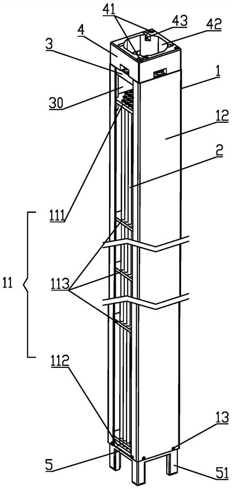
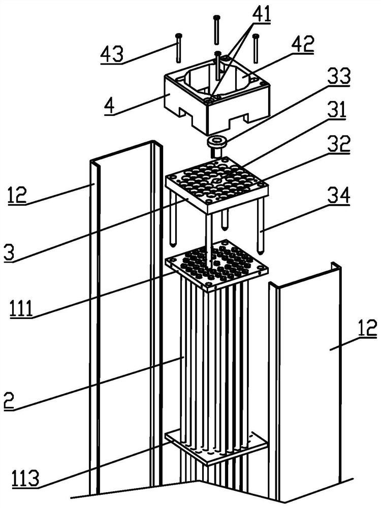
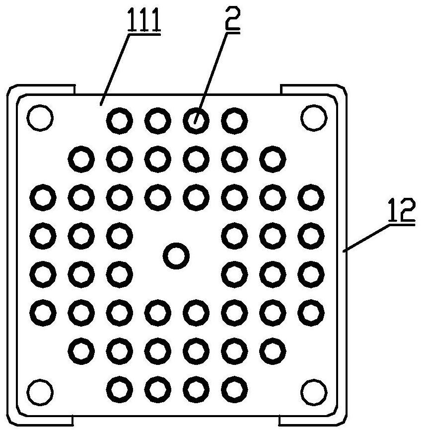

Image

  • Fuel rod inspection and storage device
  • Fuel rod inspection and storage device
  • Fuel rod inspection and storage device

Examples


Embodiment Construction

[0037] The specific implementation manners of the present invention will be described in further detail below in conjunction with the accompanying drawings. These embodiments are only used to illustrate the present invention, not to limit the present invention.

[0038] In the description of the present invention, it should be noted that the terms "center", "longitudinal", "transverse", "upper", "lower", "front", "rear", "left", "right", " The orientations or positional relationships indicated by "vertical", "horizontal", "top", "bottom", "inner", "outer", etc. are based on the orientation or positional relationships shown in the drawings, and are only for the convenience of describing the present invention and simplifying Describes, but does not indicate or imply that the device or element referred to must have a specific orientation, be constructed in a specific orientation, and operate in a specific orientation, and therefore should not be construed as limiting the inventio...


PUM


Abstract

The invention relates to the technical field of fuel inspection and repair, in particular to a fuel rod inspection and storage device. The device comprises a storage rack, a storage pipe vertically supported in the storage rack and an inspection rack supported at the top end of the storage rack. An inspection space is formed between the inspection rack and the storage rack. The inspection rack is provided with an inspection hole and a storage hole for a fuel rod to pass through, a detection piece is installed in the inspection hole, and the storage hole and the storage pipe are coaxially arranged and communicated to form a storage channel. A fuel rod can be detected by the detection piece through the inspection hole and then reaches the inspection space for inspection, and the fuel rod after inspection can be stored in the storage pipe from the storage hole through the storage channel after exiting from the inspection space and the inspection hole. A fuel rod stored in the storage pipe can also be taken out of the storage channel and then enter the inspection hole and the inspection space for reinspection. The integrated design and operation of fuel rod inspection and storage are achieved, the fuel rod inspection and storage operation time can be shortened, and long-term storage of fuel rods is achieved.

Description

technical field [0001] The invention relates to the technical field of fuel inspection and repair, in particular to a fuel rod inspection and storage device. Background technique [0002] During the operation of nuclear power plants, the fuel rods are exposed to high temperature, high pressure and high radiation environment for a long time, coupled with the influence of foreign matter in the core, vibration, and water impact, they are prone to damage and leakage. After the assessment of the nuclear power plant, the suspected damaged fuel rods can be replaced with new ones to repair the fuel assembly. Fuel rods that are suspected of being damaged are taken out of the fuel assembly, and are stored in special containers after being confirmed by visual inspection and eddy current inspection. [0003] In the prior art, most of the inspection devices for fuel rods after irradiation are special tools, and the special tools and storage containers are independent of each other. The ...

Claims


Application Information

Patent Timeline
Patent Type & Authority Applications(China)
IPC IPC(8): G21C19/32G21C19/105
CPCG21C19/32G21C19/105Y02E30/30
Inventor 许小进谢晨江章济叶琛
Owner STATE NUCLEAR POWER PLANT SERVICE
Learn More