
High-efficiency thermoelectric power generation device capable of self-sensing flow change

A technology of flow change and thermoelectric power generation, which is applied in the direction of valve operation/release device, valve device, generator/motor, etc., to achieve the effect of increasing gas temperature and reducing heat loss

Active Publication Date: 2021-10-19
BEIJING INSTITUTE OF TECHNOLOGYGY
View PDF7 Cites 0 Cited by
  • Summary
  • Abstract
  • Description
  • Claims
  • Application Information

AI Technical Summary

Problems solved by technology

The purpose of the invention is to improve the thermoelectric conversion efficiency of thermoelectric generator

Method used


Image

  • High-efficiency thermoelectric power generation device capable of self-sensing flow change
  • High-efficiency thermoelectric power generation device capable of self-sensing flow change
  • High-efficiency thermoelectric power generation device capable of self-sensing flow change

Examples


Embodiment Construction

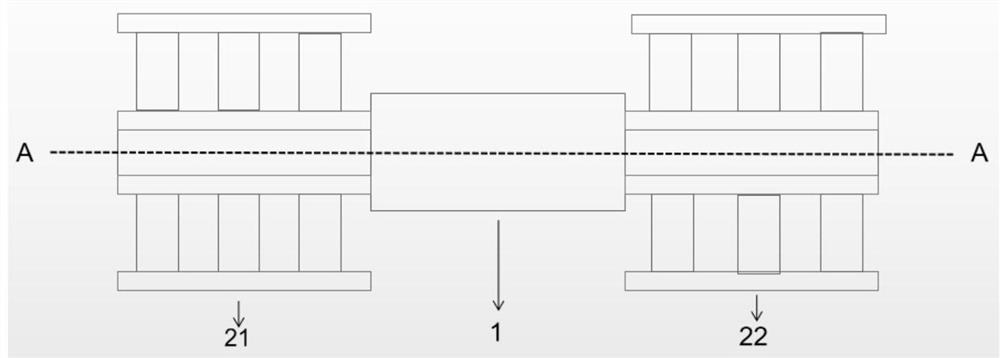
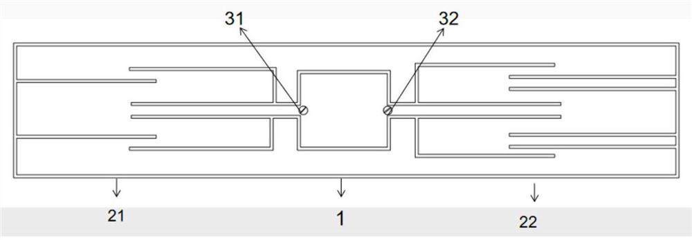
[0023] In order to better illustrate the purpose and advantages of the present invention, the content of the invention will be further described below in conjunction with the accompanying drawings and examples.

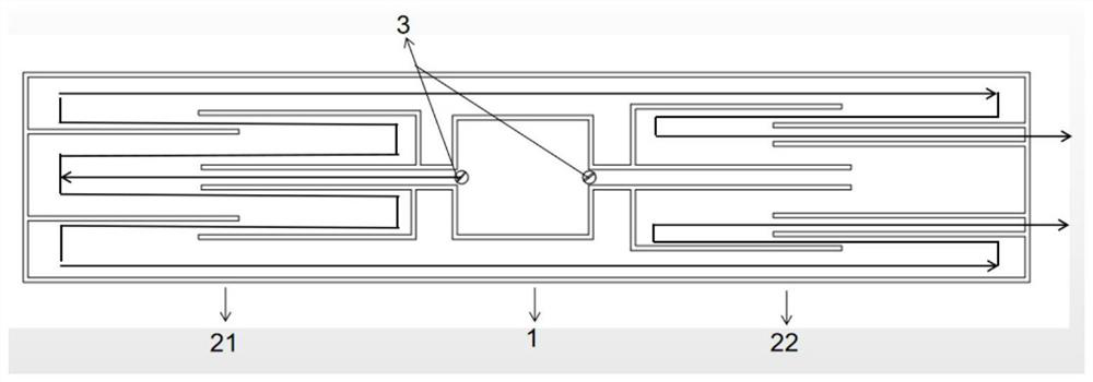
[0024] Examples such as figure 1 and figure 2 As shown, the thermoelectric power generation device with high thermoelectric conversion efficiency includes a medium-temperature thermoelectric generator heat source 21, a low-temperature thermoelectric generator heat source 22, a burner 1, and a valve 3 for controlling the air flow path; the valve 3 includes a medium-temperature thermoelectric generator heat source 21 The first gas path valve 31 of the burner 1 and the second gas path valve 32 of the burner 1 communicate with the low-temperature thermoelectric generator heat source 22 and the burner 1 .

[0025] The heat source 21 of the medium-temperature thermoelectric generator is a thermoelectric generator made of medium-temperature thermoelectric sheets; the heat ...


PUM


Abstract

The invention relates to the technical field of thermoelectric power generation, in particular to a thermoelectric power generation device with high thermoelectric conversion efficiency. The invention discloses a thermoelectric power generation device with high thermoelectric conversion efficiency, which comprises a medium-temperature thermoelectric power generator heat source, a low-temperature thermoelectric power generator heat source, a combustor and valves for controlling an airflow passage. The valves comprise a first gas path valve enabling the medium-temperature thermoelectric generator heat source to be communicated with the combustor and a second gas path valve enabling the low-temperature thermoelectric generator heat source to be communicated with the the combustor. The medium-temperature thermoelectric generator heat source adopts a thermoelectric generator made of a medium-temperature thermoelectric sheet, the low-temperature thermoelectric generator heat source adopts a thermoelectric generator made of a low-temperature thermoelectric material, and the combustor is made of a low-heat-conductivity-coefficient material. When the fuel flow is large, the first gas path valve is opened, and the second gas path valve is closed; and when the fuel flow is small, the first gas path valve is closed, and the second gas path valve is opened. The thermoelectric conversion efficiency of an existing thermoelectric generator can be improved.

Description

technical field [0001] The invention relates to the technical field of thermoelectric power generation, in particular to a thermoelectric power generation device with high thermoelectric conversion efficiency. Background technique [0002] With the deteriorating energy crisis and environmental pollution problems, if researchers are committed to finding new energy materials and new energy conversion methods. Thermoelectric power generation technology is a thermoelectric conversion method based on thermoelectric materials. It has the advantages of small size, light weight, no moving parts, no pollution, and easy integration, which makes it widely used in military, medical, and electronic product fields. Factors affecting thermoelectric conversion efficiency include temperature difference between hot and cold ends, thermoelectric materials, thermoelectric module structure, contact effect, scale effect, boundary effect, etc. Among them, the figure of merit of thermoelectric ma...

Claims


Application Information

Patent Timeline
Patent Type & Authority Applications(China)
IPC IPC(8): H02N11/00F16K31/12F16K31/44F16K31/53
CPCH02N11/002F16K31/12F16K31/44F16K31/53
Inventor 王伟马珂左正兴
Owner BEIJING INSTITUTE OF TECHNOLOGYGY
Learn More