Wearable physiotherapy instrument
A physiotherapy instrument and wearable technology, applied in the field of phototherapy lamps, can solve the problems of knee burns, inconvenient daily activities of patients, and limitation of the range of activities of patients, and achieve the effects of improving comfort, improving convenience, and enhancing practicability.
- Summary
- Abstract
- Description
- Claims
- Application Information
AI Technical Summary
Problems solved by technology
Method used
Image

Examples
Embodiment 1
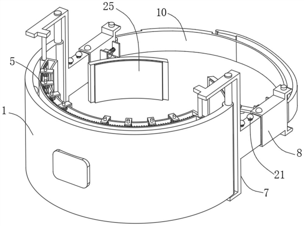
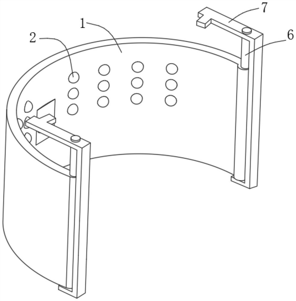
[0029] see Figure 1-Figure 3 , Figure 6 and Figure 7 , a wearable physical therapy device in the illustration, including a lampshade 1 and a plurality of small lamp beads 2 on the lampshade 1, and an arc-shaped partition 3 with the same shape as the lampshade 1 is fixed inside the lampshade 1, and the arc-shaped partition The plate 3 is provided with through grooves 4 corresponding to the positions of the small lamp beads 2 one by one, and the arc-shaped partition 3 is slidably connected with a plurality of shielding devices 5 for selectively blocking the through grooves 4. The lampshade 1 Both ends are slidably connected with a first connecting rod 6, and the first connecting rod 6 is rotatably connected with a concave frame 7, and the end of the concave frame 7 away from the first connecting rod 6 is fixed with a telescopic member 8, The end of the telescopic member 8 away from the concave frame 7 is fixed with a second connecting rod 9, and an elastic band 10 is sleeve...
Embodiment 2
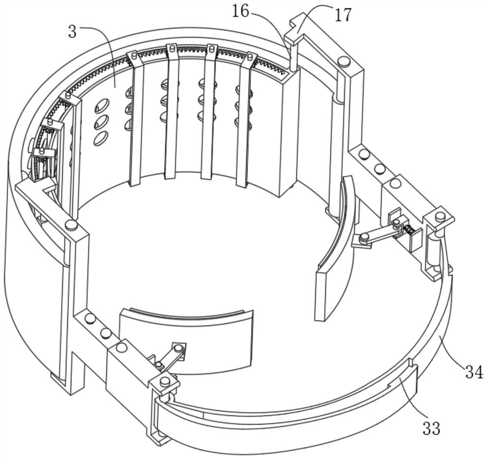
[0036] see Figure 4 and Figure 5 , this embodiment further describes Example 1, the inside of the lampshade 1 is fixed with an arc-shaped partition 3 with the same shape as the lampshade 1, and the arc-shaped partition 3 is provided with a channel corresponding to the position of the small lamp bead 2 one-to-one. Slot 4, a plurality of shielding devices 5 for selectively shielding the through groove 4 are slidably connected to the arc-shaped partition 3, first connecting rods 6 are slidably connected to both ends of the lampshade 1, and the first The connecting rods 6 are all rotatably connected with a concave frame 7, and the end of the concave frame 7 away from the first connecting rod 6 is fixed with a telescopic piece 8, and the end of the telescopic piece 8 away from the concave frame 7 is fixed with a first Two connecting rods 9 , an elastic band 10 is sleeved between the second connecting rods 9 , and the ports of the elastic band 10 can be pasted and fixed on the el...
Embodiment 3
[0042] see Figure 8 , this embodiment is further described for Example 1, the telescopic member 8 includes a slide plate 18 and a cover plate 19, the slide plate 18 is slidably connected inside the cover plate 19, and one end of the slide plate 18 is fixed between the concave frame 7, so Both sides of the end of the cover plate 19 away from the slide plate 18 are fixed with an L-shaped plate 20, and one end of the L-shaped plate 20 is respectively fixed to the end of the second connecting rod 9, between the slide plate 18 and the cover plate 19 A fixing piece 21 is provided.
[0043] Wherein, the fixing part 21 includes a telescopic rod 22, and the telescopic rod 22 is provided with a plurality, and the bottom of the telescopic rod 22 is fixed on one side of the slide plate 18, and a convex ball 23 is fixed on the telescopic rod 22, and the sleeve The end of the plate 19 is provided with a slot 24 for passing through the convex ball 23 .
[0044] When using a wearable physi...
PUM
 Abstract
Description
Claims
Application Information
 - R&D
- Intellectual Property
- Life Sciences
- Materials
- Tech Scout
- Unparalleled Data Quality
- Higher Quality Content
- 60% Fewer Hallucinations
Browse by: Latest US Patents, China's latest patents, Technical Efficacy Thesaurus, Application Domain, Technology Topic, Popular Technical Reports.
© 2025 PatSnap. All rights reserved.Legal|Privacy policy|Modern Slavery Act Transparency Statement|Sitemap|About US| Contact US: help@patsnap.com