
A fixed-length cutting equipment for industrial production of steel pipes

A cutting equipment, fixed-length technology, applied in metal processing equipment, shearing machine equipment, pipe cutting devices, etc., can solve the problems of low degree of automation and reduced production efficiency

Active Publication Date: 2022-04-26
林巧静
View PDF7 Cites 0 Cited by
  • Summary
  • Abstract
  • Description
  • Claims
  • Application Information

AI Technical Summary

Problems solved by technology

[0004] In order to overcome the shortcomings of reduced production efficiency and low degree of automation, the technical problem to be solved is: to provide a fixed-length cutting equipment for industrial production of steel pipes with high production efficiency and high degree of automation

Method used


Image

  • A fixed-length cutting equipment for industrial production of steel pipes
  • A fixed-length cutting equipment for industrial production of steel pipes
  • A fixed-length cutting equipment for industrial production of steel pipes

Examples


Embodiment 1

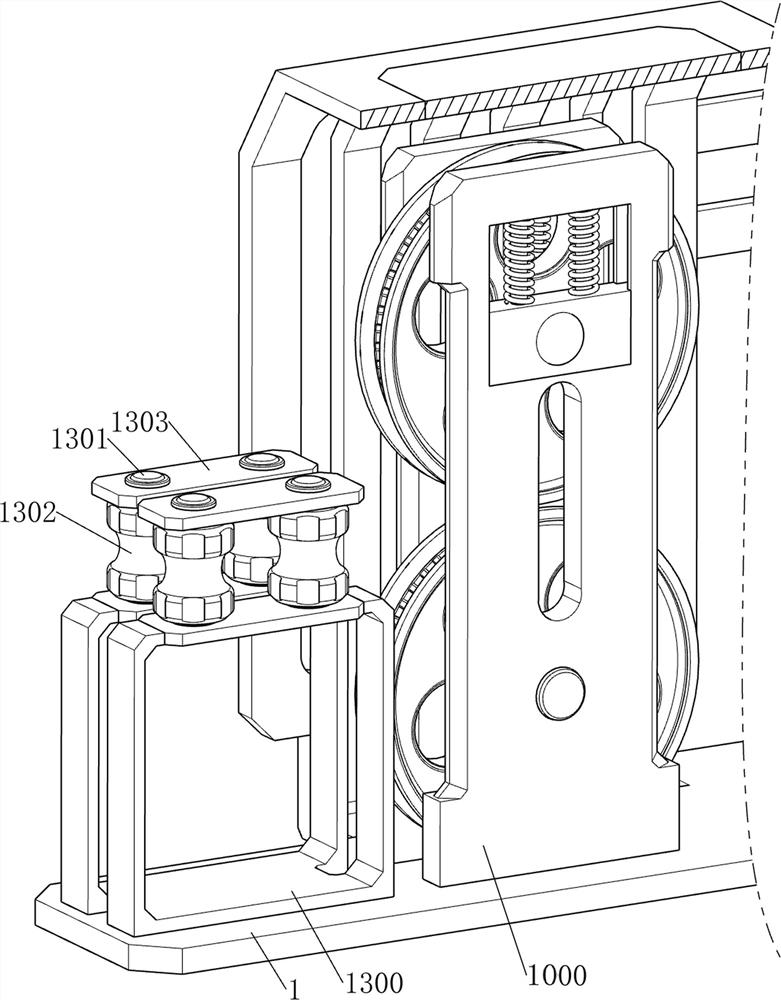
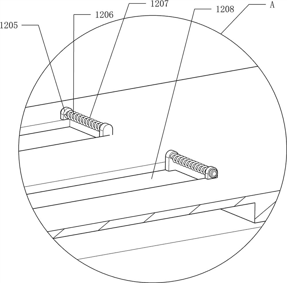
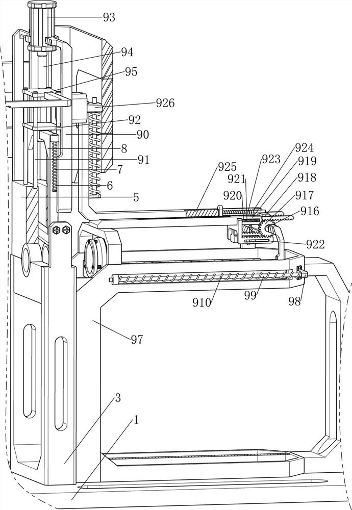
[0027] A kind of fixed-length cutting equipment for industrialized production of steel pipes, such as Figure 1-5 As shown, it includes a bottom plate 1, a protective plate 2, a first support frame 3, a backing plate 4, a guide block 5, a guide rod 6, a first spring 7, a guillotine 8, a pressing mechanism 9 and a feeding mechanism 10, and the bottom plate 1 A protective plate 2 is provided in the middle, a first support frame 3 is provided on the top right side of the bottom plate 1, a backing plate 4 is provided on the upper part of the first support frame 3, and a guide block 5 is provided on the top of the first support frame 3, and the top of the guide block 5 is symmetrical front and rear Guide rods 6 are provided, guillotines 8 are slidingly arranged between the guide rods 6, first springs 7 are arranged between the guillotines 8 and the guide rods 6, a pressing mechanism 9 is provided on the guide block 5, and a pressing mechanism 9 is provided on the bottom plate 1 Fee...

Embodiment 2

[0032] On the basis of Example 1, such as Figure 6-10 As shown, a power mechanism 11 is also included, and the power mechanism 11 includes a movable rod 1100, a second fixed block 1101, a seventh limit rod 1102, an eighth spring 1103, a fourth movable block 1104, a fifth movable block 1105, a limiter Position plate 1106, the eighth limit rod 1107, the ninth spring 1108, the second support plate 1109, the one-way gear 1110, the second gear 1111 and the third gear 1112, and the second lower pressing plate 95 is symmetrically provided with movable rods 1100 front and back, The middle part of the bottom plate 1 is symmetrically provided with a second fixed block 1101 front and back, and four seventh stop rods 1102 are arranged on the top of the second fixed block 1101, and fourth stop rods 1102 are arranged in a sliding manner between the four similar seventh stop rods 1102. Movable block 1104, the fourth movable block 1104 cooperates with the movable rod 1100, and four eighth sp...


PUM


Abstract

The invention relates to a cutting device, in particular to a fixed-length cutting device for industrially produced steel pipes. The technical problem to be solved is to provide a fixed-length cutting equipment for industrial production of steel pipes with high production efficiency and high degree of automation. The technical solution of the present invention is: a fixed-length cutting equipment for industrial production of steel pipes, including: a bottom plate, a protective plate, a first support frame, a backing plate, a guide block, a guide rod, a first spring, a guillotine, a pressing mechanism and a feeding mechanism, the middle part of the bottom plate is provided with a protective plate, the top of the bottom plate is provided with a first support frame, the upper part of the first support frame is provided with a backing plate, the top of the first support frame is provided with a guide block, and the top of the guide block is symmetrically provided with a guide rod. The present invention is provided with a power mechanism, so that people do not need to manually rotate the runners; by providing a guide mechanism, the steel pipe is guided, avoiding that when the steel pipe is too long, people need to manually support and guide the steel pipe; by providing a baffle plate, it is possible to The steel pipe falls into the charging frame more accurately.

Description

technical field [0001] The invention relates to a cutting device, in particular to a fixed-length cutting device for industrially produced steel pipes. Background technique [0002] Cutting is a process after the welding is completed. It is to cut the steel pipe formed by continuous welding into fixed length sections according to the requirements. The traditional cutting method is to cut the steel pipe directly with a cutting saw on the production line. When cutting the steel pipe, it is necessary to first cut the steel pipe Scribe marks, and then use cutting tools to cut. The steel pipes need to be measured every time they are marked. The production efficiency is reduced, and the existing steel pipe fixed-length cutting device has a poor fixing and guiding effect on long steel pipes, and people need to manually fix and guide the steel pipes, which leads to a low degree of automation of the device. [0003] Therefore, in view of the above problems, a fixed-length cutting eq...

Claims


Application Information

Patent Timeline
Patent Type & Authority Patents(China)
IPC IPC(8): B23D21/00B23D33/00B23D33/02B23Q7/00B05C3/109
CPCB23D21/00B23D33/02B23D33/00B23Q7/00B05C3/109
Inventor 林巧静
Owner 林巧静
Learn More