Automatic pipe cutting machine feeding device

A pipe cutting machine and automatic technology, which is applied in the field of automatic pipe cutting machine feeding devices, can solve the problems that the working continuity and stability of the automatic pipe cutting machine cannot be guaranteed, it is difficult to accurately control the quantity and transfer timing of pipes, and the equipment cost is high. Simple structure, high production efficiency, and the effect of improving production efficiency

Active Publication Date: 2020-05-05
JIANGSU YAAO PRECISION MASCH CO LTD
View PDF13 Cites 0 Cited by
  • Summary
  • Abstract
  • Description
  • Claims
  • Application Information

AI Technical Summary

Problems solved by technology

However, if the process of transferring the pipes from the storage rack to the conveying table is operated by a manipulator, the structure is too complicated and the equipment cost is high; if a conveying slope is set to automatically roll the pipes into the conveying table, it is difficult to accurately control the transferred pipes The quantity and transfer timing of the automatic pipe cutting machine cannot guarantee the continuity and stability of the work

Method used


Image

  • Automatic pipe cutting machine feeding device
  • Automatic pipe cutting machine feeding device
  • Automatic pipe cutting machine feeding device

Examples


Embodiment Construction

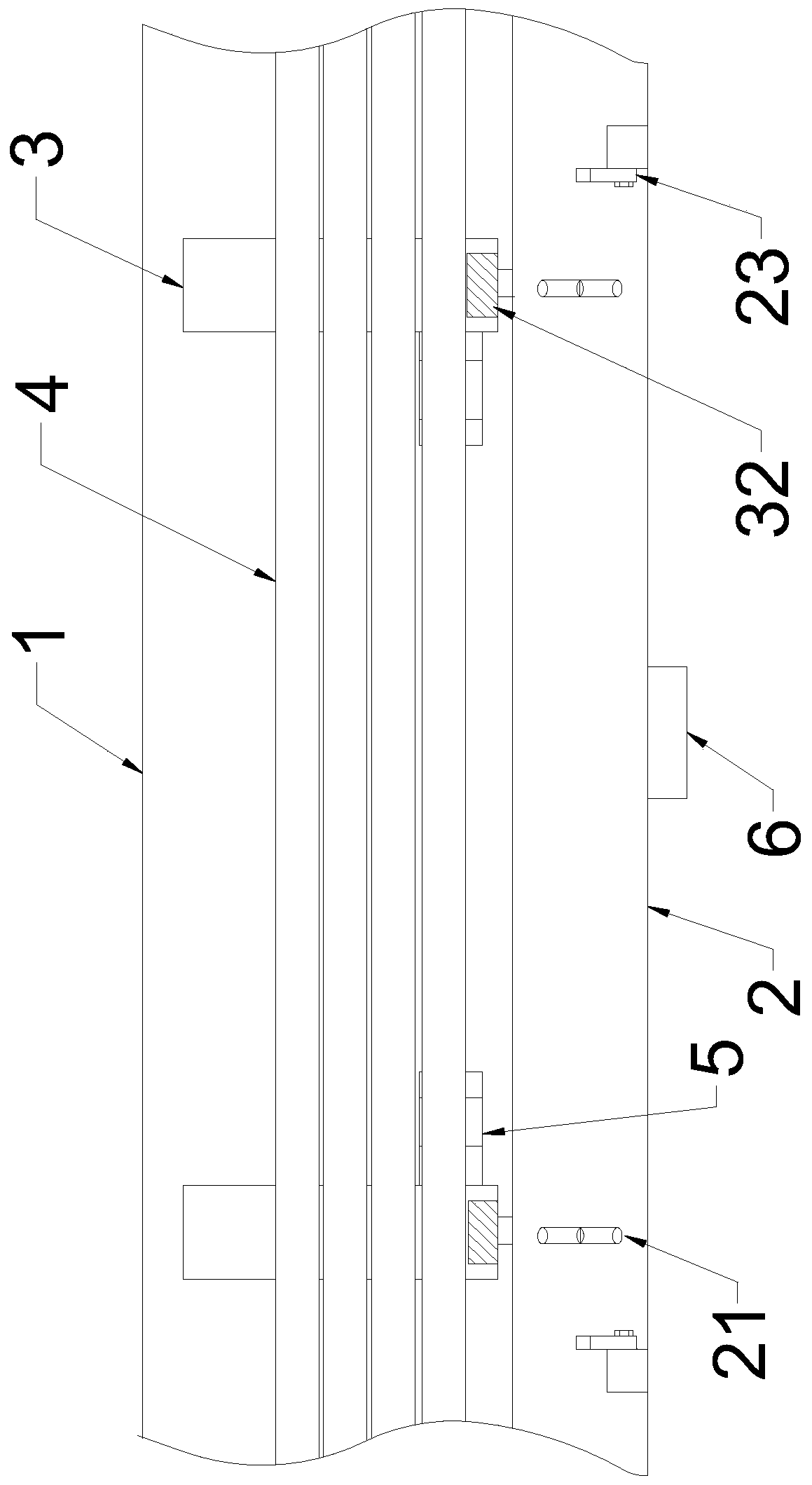
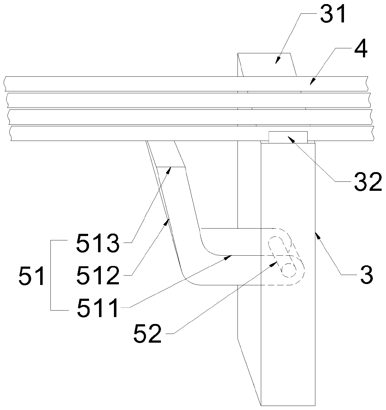
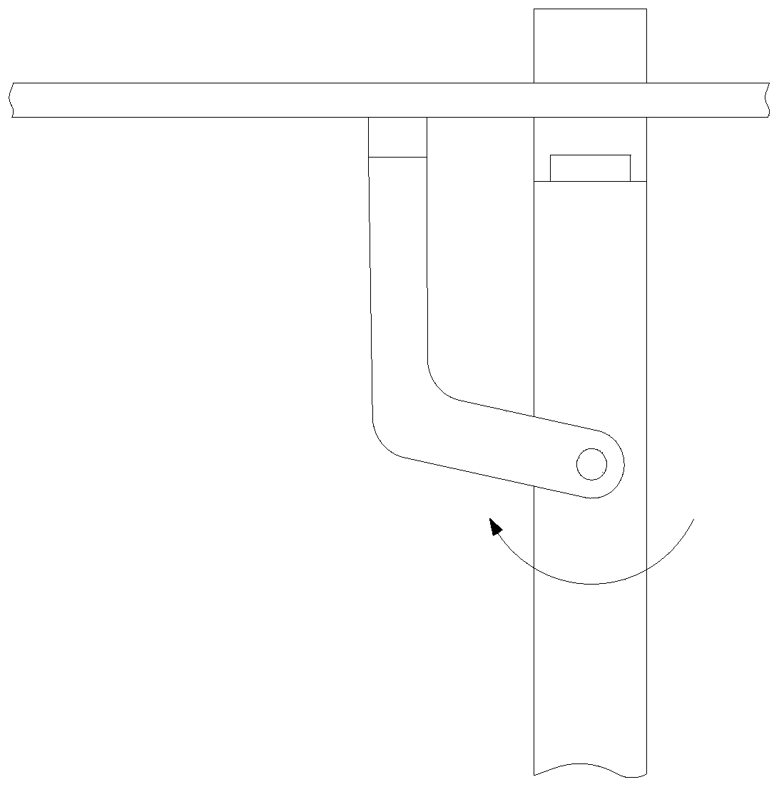
[0021] Such as Figure 1 to Figure 3 As shown, a feeding device for an automatic pipe cutting machine includes a machine platform 1, a conveying platform 2 and two storage racks 3 are arranged above the machine platform 1, the conveying platform 2 is located below the material storage rack 3, and the upper conveying platform 2 is spaced There are at least two branch pipe racks 21 for supporting the bearing tubes 4; the storage racks 3 are arranged at intervals, and the storage racks 3 include a stock top 31 inclined to the conveying table 2 side, and a plurality of bearing tubes 4 can temporarily Stored in the top of the stock 31, the end of the top of the stock 31 close to the conveying table 2 is provided with a limit block 32, the limit block 32 can resist the bearing tube on the bottom side, preventing the bearing tube from rolling down from the top of the stock 31 to the conveying table 2; the storage rack 3 is also provided with a jacking assembly 5, the jacking assembly...


PUM


Abstract

The invention provides a feeding device of an automatic pipe cutting machine. The feeding device comprises a machine table. A conveying table and two storage brackets are arranged above the machine table. The conveying table is located below the storage brackets. Each storage bracket comprises a storage top inclined toward one side of the conveying table. Bearing tubes are stored at the storage tops. The end, close to the conveying table, of each storage top is provided with a limiting block. Each storage bracket is provided with a tube jacking assembly. Each tube jacking assembly is mounted on the corresponding storage bracket in a pivoted manner. Each tube jacking assembly comprises a top plate, a rotating shaft and a motor. Each top plate comprises a horizontal connecting portion and atop plate body, wherein each top plate body is connected with the corresponding connecting portion in an inclined manner. Each connecting portion is located below the corresponding top plate body. Each rotating shaft is arranged inside the corresponding connecting portion in a penetrating manner and mounted on the corresponding storage bracket. An output shaft of each motor is connected with the corresponding rotating shaft. Each motor can drive the corresponding rotating shaft to rotate forwards and backwards, so that the corresponding top plate body rotates with the corresponding rotating shaft as the circle center. When the top plate bodies rotate upwards, the bearing tubes can be jacked. By means of the feeding device, automatic and continuous feeding of tubular materials can be achieved; and the feeding device is simple in structure, reliable in work and high in production efficiency.

Description

technical field [0001] The invention belongs to the technical field of bearing tube processing equipment, and in particular relates to a feeding device for an automatic tube cutter. Background technique [0002] The bearing tube is the raw material for bearing processing. During the processing of the bearing, the bearing tube needs to be cut into different lengths according to the actual production requirements. The commonly used pipe feeding and cutting method is: first, the pipe is manually fed into the pipe cutting machine from the jaws of the pipe cutting machine, and then the jaws of the pipe cutting machine are used to clamp the pipe, and then the pipe is cut into different shapes by the pipe cutting machine. length. This manual feeding mode of work is not only labor-intensive, but also low in work efficiency. [0003] Some enterprises have developed automatic pipe cutting machines, which can realize automatic feeding, clamping, conveying, cutting and unloading of pi...

Claims


Application Information

Patent Timeline
Patent Type & Authority Patents(China)
IPC IPC(8): B65G47/08
CPCB65G47/088
Inventor 方国祥
Owner JIANGSU YAAO PRECISION MASCH CO LTD
Why Eureka
Try Eureka